Another step-down frame question ('49 Brougham)
Hi All, I once again need to summons the Hudson Nation. Thanks for the help on my prior post about the cracked frame fix.....I'm about to do that, but thought I should first pose this question.
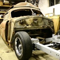
My '49 brougham has definitely seen some abuse, so I want to make sure the front sub-frame isn't bent. Pictures of the car prior to removing the front clip seem to suggest the frame may be bent upwards since the gap between the passenger door and the front fender tapered from ~3/8 at the bottom to 0.0" at the top indicating the frame or fender or core support (or some combination of) is bent upwards. I think it would be relatively easy to check the height dimension on an undamaged original car, or someone may just know it already (see picture). Thanks again for your help.....hopefully you won't get tired of me asking questions :-)
Lee
0
Comments
-
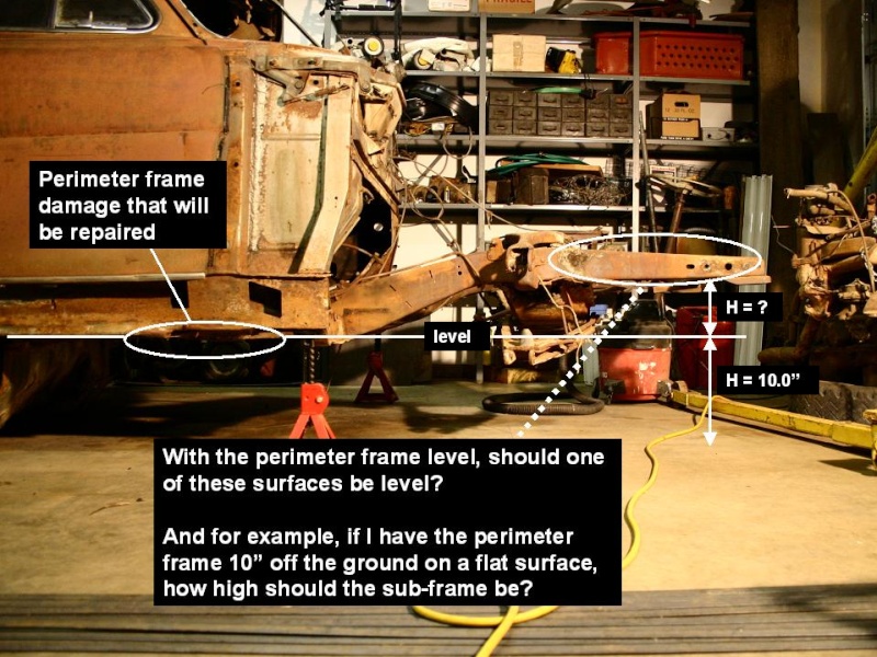
I've been thinking about this. If someone could measure up from the floor to their perimeter frame in 4 places (near the wheel openings), and measure up from the floor to the subframe (near say the bumper bolts), as long as the floor was flat, I could calculate the relative subframe height (using CAD software). The only requirement would be that the floor was flat (the floor or the car would not have to be level). I don't know of anyone in my area with a stepdown or I would do it myself. Is anyone out there in the seattle/tacoma area that wouldn't mind me taking some measurement off their car?
Any other comments or suggestions???
Many thanks,
Lee0 -
Given your description and that the alignment problem is on the same side as the "frame repair" I'd guess the cracked weld caused that side to sag a little which would have created the gap you mentioned.
If the drivers side door/fender does line up - I'd X-measure the front frame rails from the top using points of reference that match on both sides to start...0 -
Im showing 4 15/16" for your H measurement0
-
stateline wrote:Im showing 4 15/16" for your H measurement
Awesome....thank you very much for taking the time to measure. I'm on my way out to the shop right now to see how I compare to your 4 15/16" number. I'll let you know how it turns out.
Thanks again,
Lee0 -
To the best of my ability, I calculate my H to equal 6 3/8" which suggests my frame is bent upward by well over an inch. Hmm....now what. I suppose I could heat the cross-beam below the firewall and try to pull the subframe back down? Or if I weld on a new FatMan Fab stub frame I could just make up for the difference in height when I weld it on?? I imagine it's not real critical since I can shim the core support bolt if I need to for fender alignment and slot the bumper holes.....any thoughts? Thanks for all your help.
Lee0 -
Before going too far, I would double check the level line and the point you are measuring to so that they are exactly tto the same point. A little bit off will make a big difference in the dimension. Also, you should check the opposite side of your vehicle and compare the numbers. If they are close (I believe the tolerances should run a 1/4 inch or so), you may not have much of a problem. If they are way off, you may have a twist in the subframe which would need to be corrected.
Does any one have the frame dimensions and tolerances from a body repair manual?
Good Luck!0 -
0
-
lsfirth wrote:To the best of my ability, I calculate my H to equal 6 3/8" which suggests my frame is bent upward by well over an inch. Hmm....now what. I suppose I could heat the cross-beam below the firewall and try to pull the subframe back down? Or if I weld on a new FatMan Fab stub frame I could just make up for the difference in height when I weld it on?? I imagine it's not real critical since I can shim the core support bolt if I need to for fender alignment and slot the bumper holes.....any thoughts? Thanks for all your help.
Lee
NOOOOOOOOOOOOOOOO! :eek:
NEVER use heat on a frame of any type to try and "bend" or pull back into shape!
I see you're in Renton, I'm in Port Orchard so I can come by and take a look at the frame and give you some suggestions.
BTW - I also have availability to a professional frame rack, I can schedule to use it on the weekends or evenings for a nominal fee (the shop is in Kirkland - I can tow the or you can...)
Then we could put it on the rack and use transoms to check the measurements.
Let me know what you think, probably wouldn't be more than a couple hundred tops - if we need to make a pull.
BTW - I could have sworn I've seen some specs on the "frames" maybe even blueprints? If someone has a readable copy that would help.0 -
Okay, now we're getting somewhere.....let me carefully re-check my frame to the drawing. I have been checking both sides and taking the average. The passenger side has the cracked weld at the intersection of the cross-beam and sub-frame and is relatively flexible (so I can move it up and down a 1/2" to get it the same as the drivers side before I weld the crack.....but I was worried about the whole frame being bent up. With the frame drawing in hand I should be able to really verify now if my frame is bent. I didn't know the drawings were available.....I certainly owe a 6-pack to HeartofTexas!
Many thanks!!!!
I'll let you know what I find out.
Dan - thanks for the offer of the frame straightening help.....hopefully we won't have to resort to that, but I'll keep that in mind. I have access to a trailer and I have a truck, so it would only be the time on the rack. Thanks again!!
Lee0 -
Lee-
Take advantage of Dan's offer. Best decision you'll make, I assure you.0 -
Okay, here's the latest, when I tried to enlarge the link that Ken gave me, I still couldn't make out the dimensions very well. So I went to his site and groused around a little more and found the same picuture but at a much higher resolution. Here's his other picture:
http://hudsonrestoration1948-54.com/images/stepdownframechart.JPG
Now this indicates that my "H" dimension should be 5 19/32" (actually to the lower surface of the core support flange from what I can tell from the picture). This is certainly closer to my 6 3/8" measurement. So now I'll take the real measurement from the center of the bumper bolt hole. I think I'm not in too bad of shape.
What I've found to be very useful is an inexpensive laser level. Like this:
http://shop.ebay.com/items/bushnell%20laser%20level?_dmd=1&_sop=12 This removes any doubt about the floor being level since you can set up the level and measure down from the frame to the laser line and accurately adjust the height by shimming the jackstands. I think I'm on my way to having everything dialled in.
The thing I'd like to verify is if the 1949 frame uses the exact same measurement as the picture since the picture indicates 1952 thru 1954 models. Does anyone know where this picture came from? Because if I look closely I can see where other drawings of the frame had bled through to this drawing. The several pages before and after this page in the book look like they would be very helpfull as well.
Thanks Everyone and I'll give periodic updates as I go. I really appreciate everyone's help on my "little crisis".
Lee0 -
lsfirth wrote:Okay, here's the latest, when I tried to enlarge the link that Ken gave me, I still couldn't make out the dimensions very well. So I went to his site and groused around a little more and found the same picuture but at a much higher resolution. Here's his other picture:
http://hudsonrestoration1948-54.com/images/stepdownframechart.JPG
Now this indicates that my "H" dimension should be 5 19/32" (actually to the lower surface of the core support flange from what I can tell from the picture). This is certainly closer to my 6 3/8" measurement. So now I'll take the real measurement from the center of the bumper bolt hole. I think I'm not in too bad of shape.
What I've found to be very useful is an inexpensive laser level. Like this:
http://shop.ebay.com/items/bushnell%20laser%20level?_dmd=1&_sop=12 This removes any doubt about the floor being level since you can set up the level and measure down from the frame to the laser line and accurately adjust the height by shimming the jackstands. I think I'm on my way to having everything dialled in.
The thing I'd like to verify is if the 1949 frame uses the exact same measurement as the picture since the picture indicates 1952 thru 1954 models. Does anyone know where this picture came from? Because if I look closely I can see where other drawings of the frame had bled through to this drawing. The several pages before and after this page in the book look like they would be very helpfull as well.
Thanks Everyone and I'll give periodic updates as I go. I really appreciate everyone's help on my "little crisis".
Lee
The frame pictures on my website are scans of the frame charts found in a Chilton Wreck Estimator manual. The volume from which this picture came was minted in 1957. The back side of that page has the 53-54 Jet frame specifications. This picture does indeed cover the 52-54 Hudson. I do have several editions of the Chilton Body and Frame Manuals, and after checking I have found a 1948 to 1950 Frame chart. If you PM me here or email me with you email address, I will send you a high resolution copy of the manual page.
If you would like to own a copy of this manual there are several for sale on eBay at this time ... one example has a starting bid of < 6 dollars!
http://cgi.ebay.com/ebaymotors/Chiltons-Motor-Age-Body-Frame-Manual-1946-1950-As-Is_W0QQitemZ150344819318QQcmdZViewItemQQptZMotors_Manuals_Literature?hash=item23013fe276&_trksid=p4506.c0.m245&_trkparms=65%3A1%7C39%3A1%7C240%3A1318QBWk~$(KGrHgoH-CMEjlLl)s+(BKB6bhn)P!~~_2.JPG) 0
0 -
Rambo, why not heat it to straighten?0
-
bent metal wrote:Rambo, why not heat it to straighten?
Easy, get the metal too hot or overwork it - you will make it brittle - not a good thing for a frame component or unibody sheet metal section that is structural in nature.
Even welding to a frame should be done with a certain amount of care and planning... proper cleaning, fish-plating(if needed), pre-heating etc...
In the end - it's the way I was taught 29 years ago and I'm sticking with it 0
0 -
Heart_Of_Texas wrote:The frame pictures on my website are scans of the frame charts found in a Chilton Wreck Estimator manual. The volume from which this picture came was minted in 1957. The back side of that page has the 53-54 Jet frame specifications. This picture does indeed cover the 52-54 Hudson. I do have several editions of the Chilton Body and Frame Manuals, and after checking I have found a 1948 to 1950 Frame chart. If you PM me here or email me with you email address, I will send you a high resolution copy of the manual page.
If you would like to own a copy of this manual there are several for sale on eBay at this time ... one example has a starting bid of < 6 dollars!
http://cgi.ebay.com/ebaymotors/Chiltons-Motor-Age-Body-Frame-Manual-1946-1950-As-Is_W0QQitemZ150344819318QQcmdZViewItemQQptZMotors_Manuals_Literature?hash=item23013fe276&_trksid=p4506.c0.m245&_trkparms=65%3A1%7C39%3A1%7C240%3A1318
Hi Ken, I'll PM you. Huge thanks!!!
Do you think the 48-50 frame chart should be put on your web site?
Lee0 -
okay, here's a few new pics of my frame repair. Got the crack ready to weld and cut out some gussets to strengthen the joint.....they're ready to weld in. The frame dimension chart from Ken Cates has been invaluable. I leveled everything up with my laser level and all the dimensions check out. Whew....no bent frame.
Here's some pics:
crack cleaned up and ready to weld
Here's the set of gussets I cut out of a 2x6 box tube.....there's left and right side pairs.
Here's a test fit of the gussets on the passenger side (outboard)
passenger side inboard
Here's a zoomed out shot 0
0 -
Okay, I welded up the crack. Now I can finish fitting the gussets and weld those in. I bought a few cans of weld through primer. Made a sample weld....seems to work pretty good. I'm going to primer the area under the gussets since I won't be able to paint that area later....it'll be totally enclosed (which maybe suggests I don't need to paint it???). I'll post more pics of the gussets when I get them welded in.

Now I finally got all the gussets welded in place.....not the prettiest welds ever, but I got good penetration....should be plenty strong. Now I can continue with the rest of the project. I'll have to use some different break and clutch pedals now since the gussets block the original motion. I'll figure something out.
 0
0 -
Hudson308 wrote:Welds look good, Lee!
That weld-thru primer works fine unless you plan to topcoat it. I haven't found paint yet that doesn't want to jump right off of it.
Is it possible to create a flat spot on that driver side inboard gusset for a shortened clutch pivot bracket? IMHO you could have left that chunk out... yours is the first cracked subframe I've ever seen.
Hey, waitaminit.... is this the same subframe you're taking a sawzall to in the "Street Rods" post? :eek:
Yeah, where I'm going to top-coat, I've sanded off all the weldthrough primer. I agree.....stuff doesn't stick to it very well!! I'm surprised that cracking of the frame here isn't more common.....it looks like kind of a weak point to me. Anyway....I shouldn't have that problem anymore")
You weren't supposed to talk about the sawzall in this post......ssshhhhh. Now I'm going to get killed!!!0 -
lsfirth wrote:
If you e-mail Walt he can send you the 1948 and 1949 frame picture from his original Hudson Body Service Manual. Don't know how to send here. I've scan the picture and will send it to anyone that wants it. waltmordenti@aol.comHi Ken, I'll PM you. Huge thanks!!!
Do you think the 48-50 frame chart should be put on your web site?
Lee
Why put het then say leave it off?? Walt.0 -
walt's garage-53 wrote:Why put het then say leave it off?? Walt.
Walt, it foils the many automated e-mail address grabbers that search the web.0 -
Park W wrote:
Thanks, I'll remember that and add it to all my future writings. Walt.Walt, it foils the many automated e-mail address grabbers that search the web.0 -
walt's garage-53 wrote:If you e-mail Walt he can send you the 1948 and 1949 frame picture from his original Hudson Body Service Manual. Don't know how to send here. I've scan the picture and will send it to anyone that wants it. waltmordenti@aol.com
Why put het then say leave it off?? Walt.
Hi Walt,
Ken had emailed me the scanned image of the 48-49 frame dimensions. They are indeed identical to the later stepdowns, just a few little things are different. The hi-res image I mentioned in an ealier post is the best one.....you can read all the dimensions easily.
Not sure if I mentioned this earlier, but I used a "cheapy" laser level to check the dimensions. I had the car on jackstands and positioned the level near the front of the car. I then adjusted the level so that it projected a plane parallel to the frame at the rockers (keep in mind the frame changes height near the front wheel and near the back wheel - so I "leveled the level" using the mid section of the rocker frame under the doors). I could then easily measure down to the laser from any point on the frame and determin the relative heights at any location. One key thing to keep in mind is that the "base line" on the drawing is at the lower side of the perimeter frame at the foreward end near the front wheel.
Lee0 -
Hudson308 wrote:You needn't fear violence from us.... unless you stop posting pics of your progress! Then things could get ugly.... :eek:
Ha Ha.....okay. This is like the movie "speed"......as long as I post progress you'll let me live
I put a few more pics in the street rod section.
Lee0


This discussion has been closed.
Categories
- 37K All Categories
- 115 Hudson 1916 - 1929
- 21 Upcoming Events
- 94 Essex Super 6
- 28.6K HUDSON
- 576 "How To" - Skills, mechanical and other wise
- 995 Street Rods
- 151 American Motors
- 180 The Flathead Forum
- 49 Manuals, etc,.
- 78 Hudson 8
- 44 FORUM - Instructions and Tips on using the forum
- 2.8K CLASSIFIEDS
- 609 Vehicles
- 2.2K Parts & Pieces
- 77 Literature & Memorabilia
- Hudson 1916 - 1929 Yahoo Groups Archived Photos