Installing Rack & Pinion Steering on my 51 Hudson

DISCLAIMER: This is purely my adventure with my project and I am not recommending that anyone use this as instructions for doing this to their car. I do not accept any liability for others doing so.
This project is turning into an interesting journey of wanting performance and at the same time be totally safe when driving it. I wanted to achieve both of my goals without compromising either one of them. This is a work in progress so just sit back and read as I make more progress.
I first looked into the aftermarket units that were designed for the 1980 Camaro front clip. Their prices were $1000+ and it was something I felt I could afford.
The upside of all these units are:
1. They are all pre-engineered and tested.
2. You can vary the number of parts packages you want to purchase from them.
3. They are all an easy bolt-in.
4. You are not flying by the seat of your pants wondering if your creation will work.
The downside of these units (In My Opinion for my specific wants) were about the same with all the manufacturers.
1. They are all proprietary units which would cause a problem if you were in the middle of nowhere on a long trip and had a malfunction and couldn’t get parts or service quickly. I wanted my unit to be an off the shelf part that I could purchase at just about any auto parts store in the nation.
2. My design in some instances reduces the number of moving parts which in turn means less parts to break or wear out.
3. I wanted the unit to set as far back as possible for weight distribution. I know, I know, it isn’t that much weight but I am also moving the radiator and A/C condenser back as well. As a plus, this will give me a little more area in front of the radiator to work in this area when needed.
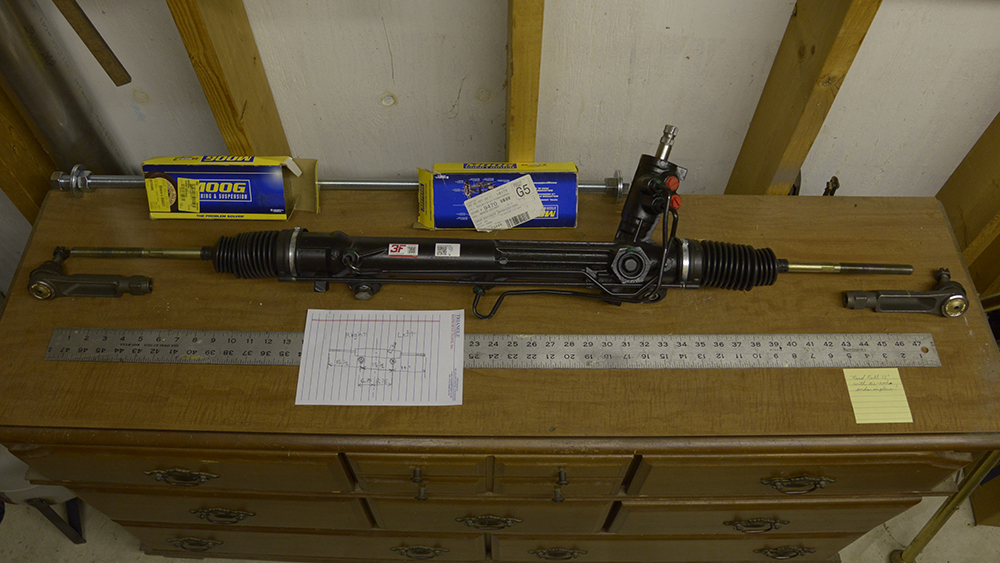
By studying of photos I had found, watching YouTube videos and other research I started narrowing down what I could or could not use for my application. I happened to run across an article by the Hollister Road Company of how they used a 1986 T-bird rack. The instructions were well written and was accompanied by photos. My thanks to you guys in Houston! This appealed to me because I had also used a Mustang II unit in my first car that I built and also that the width of the rack was ideal for my installation needs. Please note there are 3 different models of this rack so for my application I purchased the T-bird rack A1-Cardone rebuilt 22-203A. This will bring your turning from lock to lock similar to the Hudson. The only issue you will run into on this installation is having a Ford rack with a Chevy PS pump. The PS pump will need a pressure reducer valve which is readily available from different vendors.
TO BE CONTINUED!
Comments
-
Chaz I thought of you today. We were in Hamilton Tx at a car show when I saw this car.
Cheers Ken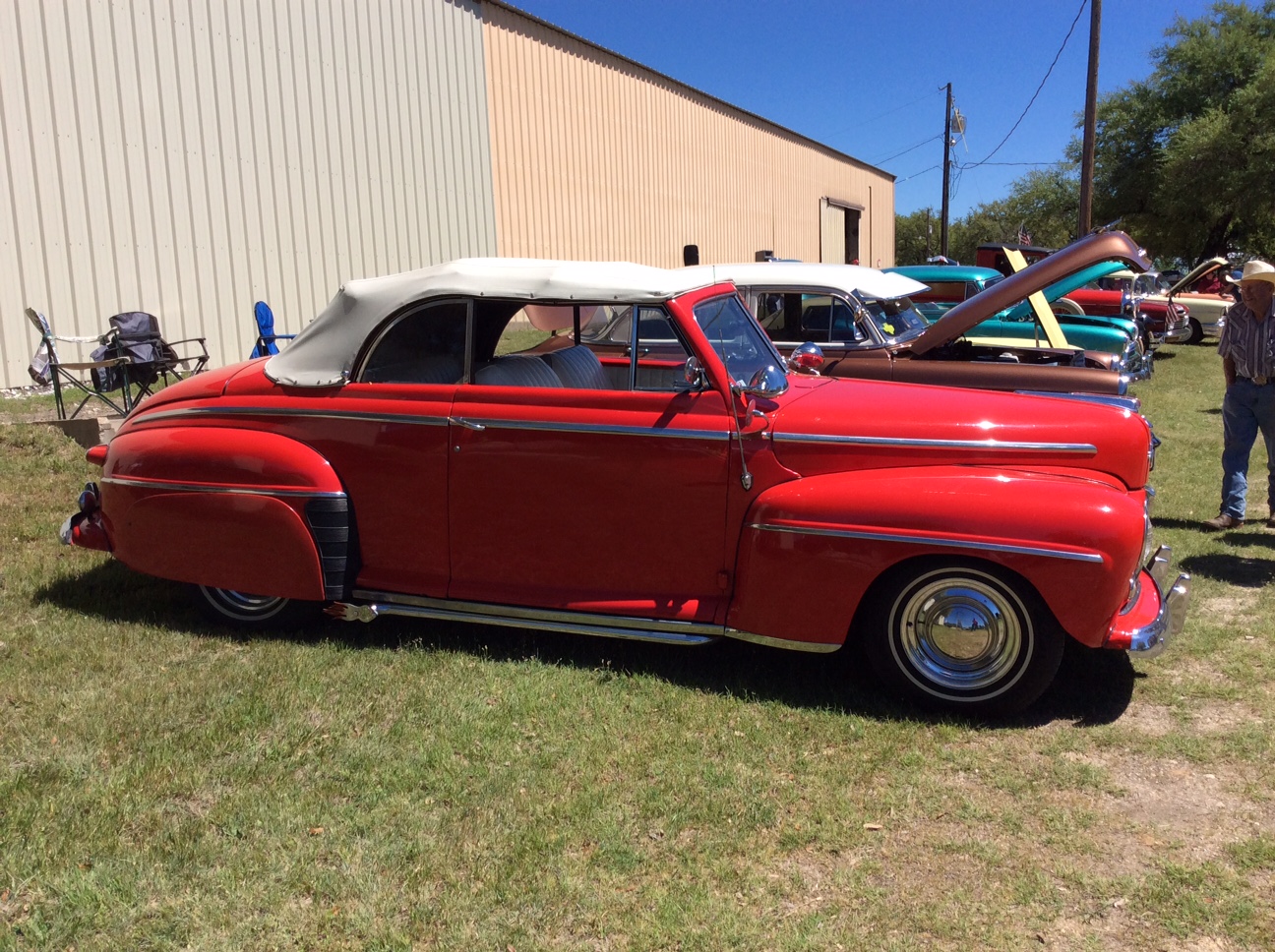 0
0 -
Oh yeah, that's Clarence and Nelda's car. They live just west of Hamilton over in Comanche, Tx.
This is ours winning both Best in Show and 1st place in custom. This is the one with a MII rack and pinion steering unit.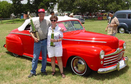 0
0 -
Now that I had purchased the rack that I wanted to use, I had to somehow establish a median Ride Height of the finished car which took quite a while to come up with. I tried getting some sort of dimension for the average ride height from my local Camaro Car Club but to no avail. I tried a couple of the Camaro forums but that was met with lack of information or they kept wanting to inject various variables like is this with cut springs, are you running 2” dropped spindles or is it an xyz model of that year Camaro or does it have a big block, a small block or a 6 cylinder. Gee guys, just you plain everyday average Camaro! I gave up on that! I finally found a side view sketch the Camaro frame on the internet that gave me a dimension of 9-1/8”. I finally ran across a Camaro sitting in a parking lot and crawled under it and got a dimension from the top of the clip down to the ground. Yes, I did get permission! This dimension was 9” which translates to 7” at the bottom of the rocker panel of the body to the ground. By using that figure of 9” compared to the side view sketch, and a dimension from one of the club members “driver”, I felt comfortable to continue to the next step. Once I got a dimension that I was going with, I needed to get the un-sprung weight of the car down to the “finished” ride height. How do you do that? I made a very simple height gage. I had a 9” length on one end and then bent it over at a 90% angle. This short bend would then rest on top of the frame hanging down. When the long piece touched the ground, the frame would then be at “ride height”. A couple of small details: Make sure your tires and properly inflated to their recommended driving pressure and the car body had the proper angle for your proposed driving stance. Some people like “tail draggers” while others like the California rake, while others prefer totally stock height. It’s your call!
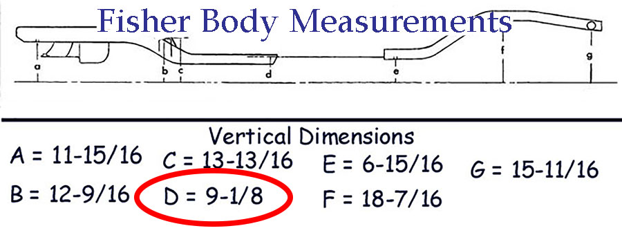
SIMPLE HEIGHT GAGE 0
0 -
When i was looking at front end options I had similar issues about ride heights etc.
I found contacting suspension/shock stores the best method as they generally had the stock ride heights on file for most options i could think of.
Spent weeks if not months trying to figure out what to use and research. In the end i got mine custom made for the Hudsons weight, to my desired ride height/shocks i wanted to use, intended drive style, sump placement, breaks, geometry, bump steer and list goes on...
Some options i looked at although good and much cheaper than custom made had been made for much lighter cars.0 -
So........How do I get my car leveled out at the finished ride height I wanted? Don't laugh guys! I did it the old fashioned way. LOWERING BLOCKS! I kept adding concrete blocks in every clear space I could find until the car body settled down into what I wanted. I even had weights on the outside across the front bumper mounts. Crude? Yes! Did it work? Yes! HaHa!
Peace,
Chaz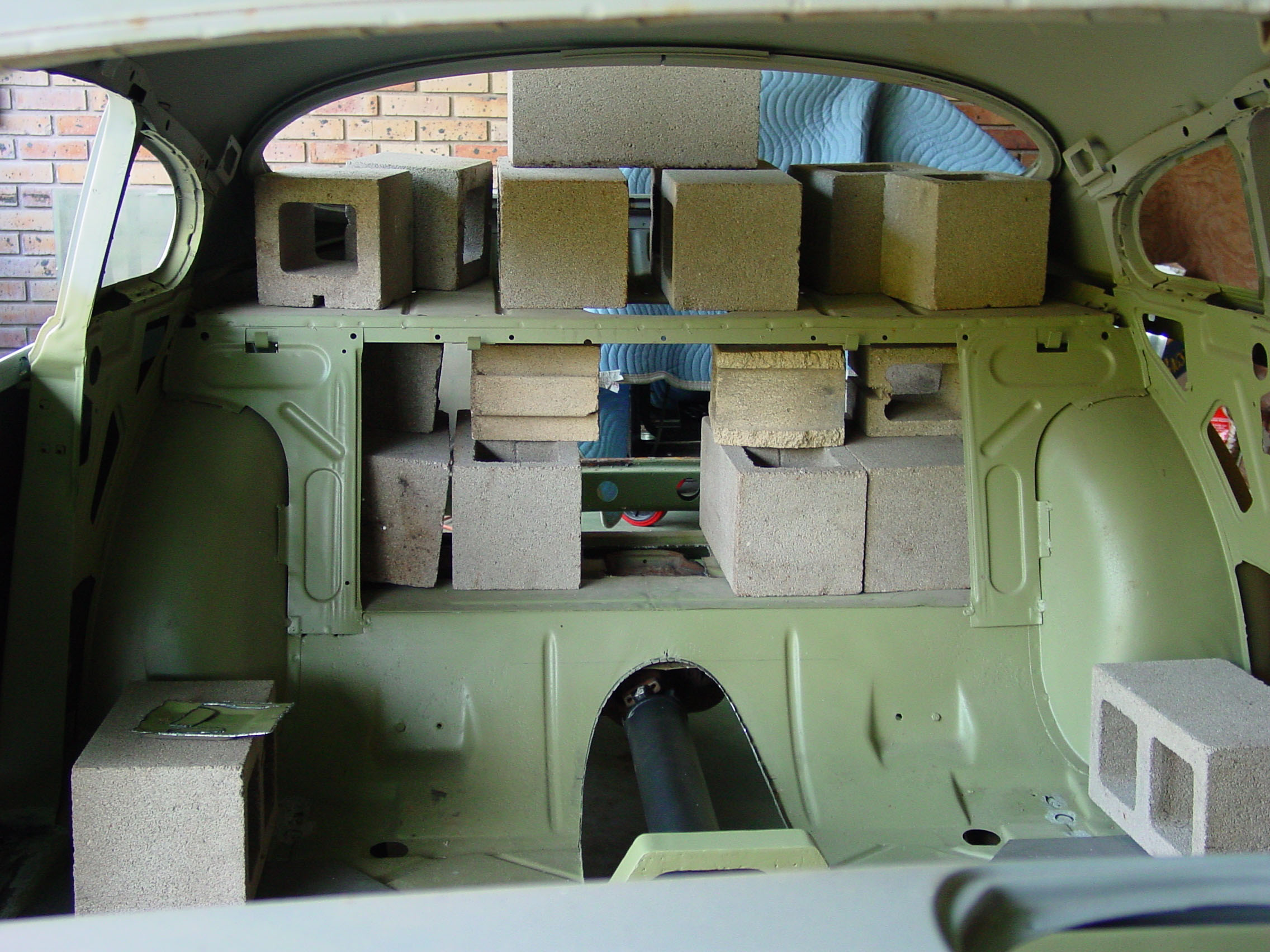 0
0 -
Onward! Now that I have the car at completed ride height, I needed to establish the horizontal center line of where the rack will be permanently attached. I made a temporary tie rod connecting both spindles. This gave me a straight line between the 2 pitman arms that I could work from for the correct alignment on both horizontal and vertical axis. This will help to prevent bump steer.
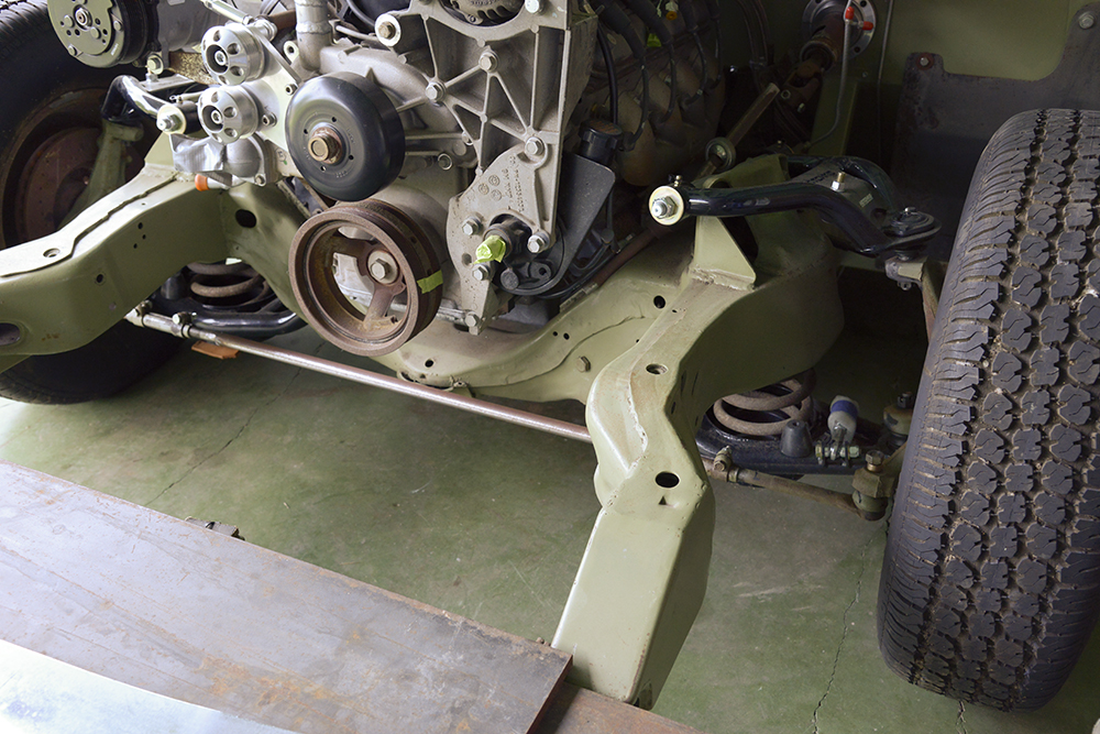
With that done, I now made 2 temporary mounting brackets, one for each side of the frame. These will clamp around the temporary tie rod (eventually the rack) to give me 2 mounting points to hold the rack in place while I am making the new permanent mounting brackets.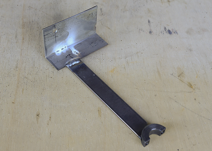
0 -
-
Was there a problem with gear box clearance?
Capt Chrysler
oops! Set Back, I got it.0 -
WHAT? I don't understand what you are asking! Please clarify!0
-
mrsbojigger,
I missed the part about "I wanted the unit to set as far back as possible for weight distribution." I was thinking with all the fast ratio Camaro gears boxes on the market. It would be easier to go that route. But, as a gearhead the easy route is always less traveled.
Capt. Chrysler0 -
Hey Capt,
Thanks for the clarification.
I think the next 2 photos will give a better understanding of where I am going with this by using the temporary alignment brackets seen in previous photos. In the next step, I removed the temporary straight tie rod and replaced it with the "Real Thing". As the real rack & pinion unit was placed into position, everything aligned perfectly with just a few tweaks of the outer tie rod end on the left side. The temporary alignment brackets will eventually be removed once I make the permanent rack mounting bracket.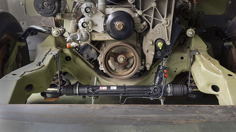
Here you see how the steering column shaft has clearance going up over the frame and clearing the left exhaust header. Those long all-threads are for alignment purposes only!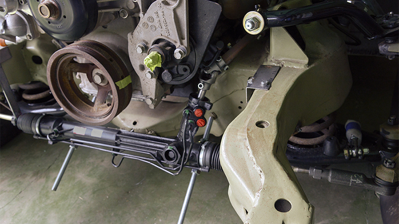
The next project will be making templates for the permanent rack mounting bracket which will span across in front of the frame yoke attaching to the 2 frame rails. I will start by making rather loose 1/4" plywood pattern and then fine tune it. Then this will be transferred to 1/4" ABS plastic so I can have a real working mounting bracket that I can take in and out to make sure everything works correctly. From that finished ABS pattern, I'll cut the final parts from steel and weld them together. This will take some time so I will not be adding anymore information to this post for a while until I have something to show.0 -
-
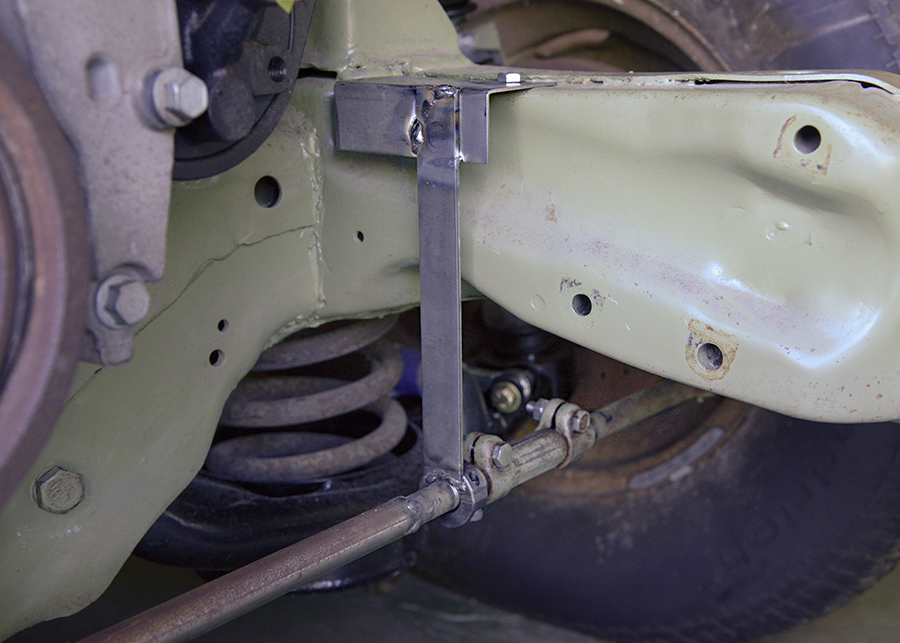
Hey Capt.
Oh yeah! I have seen it. I am still going with my '86 T-bird on the project. I will save about $1000 plus I have the satisfaction of designing the brackets myself. 1. I like the creative process, and 2. This is an off the Rack unit (pardon the pun) which means that I can go into any city and any auto supply across the U.S. and purchase another one if needed for a mere pittance and it will bolt right in. Also, I always try to design my projects so they can be easily worked on later after the car is finished.
Peace,
Chaz
First round of template design. More fine tuning later.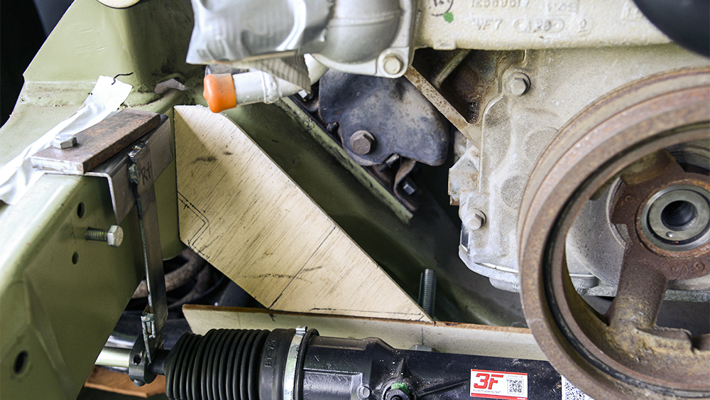 0
0 -
Will this rack give you enough travel so the car will turn stop to stop?
I have worked on a couple Chrysler torsion bars (long bars) front ends that have been converted to racks. They drove ok, wouldn't turn in a country mile. Simple fix after I found the "right stuff".
Keep us posted!
Capt. Chrysler0 -
Well it can't be any worse than our Ford Taurus! I hate parking that car. This rack is being used successfully on many Chevy C-10's with no problems. You know I did check this out before I made the decision to use it. Guess we'll find out won't we!
Peace,
Chaz0 -
It's just math! But, some folks get locked up pretty tight!0
-
Thats Nice!0
-
This is the second in a series of refinements of the plywood mounting bracket template before making the final steel one. Its much easier working with wood, glue and tape than having to modify the final steel version. I learned that lesson many years ago.
Peace,
Chaz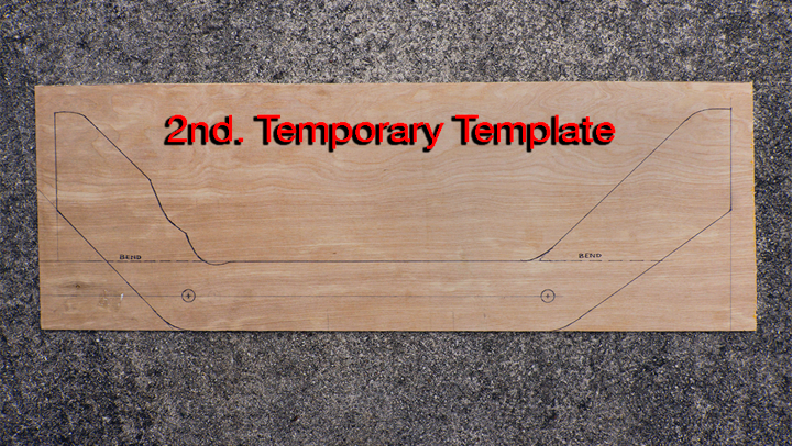
0 -
Appreciate the research work.
Very detailed, TKS.
Problem is: I am to old to start all that now. But I have every issue of Street Rodder.0 -
Hey,
Did you guys ever think that I may enjoy designing and making my own parts? Years ago, I headed up an engineering drafting department where we designed and manufactured brackets for foreign cars.
Peace,
Chaz
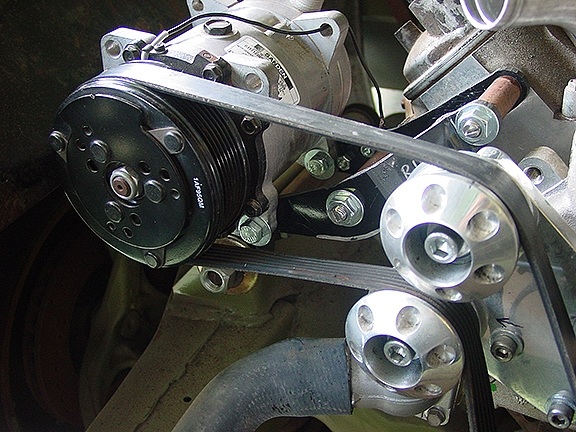
Example of one of my brackets which will be powder coated. It sets the compressor out far enough to be able to remove the right side valve cover, use the stock belt length, clear the top of the inner fender panel and have the A/C hoses run comfortably along the upper part of the inner fender panel and thru the firewall.
0 -
Nice wrap on the AC compressor!0
-
One thing, I believe you are using two u-joints in the steering column, I have similar set-up in my '55 Studillac. (I used Borgeson u-joints, which are good). Expect some play through the u-joints and some "clicking" sounds0
-
Thanks Capt. and Dougson!
Update: The 3rd Gen template was finished with all the final details, went to scanning today and the file is being drawn up in a CAD program. From there it will go to being cut out by either a Water Jet or Laser cutting machine. Probably the Laser. While this is in progress, I have "changed hats" and back working on the dash and some electrical projects.
Peace,
Chaz0 -
Chas - Truly a craftsman of all trades. Love to see your updates and progress!
0 -
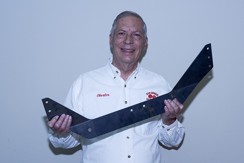
I now have the Laser cut 3/16" flat steel horizontal R & P unit mounting bracket. It also has the 18 degree bends in their correct locations on both sides. The bracket will be placed into position so I can make the templates for the 2 outer vertical mounting brackets that will be welded to the frame rails.
Peace,
Chaz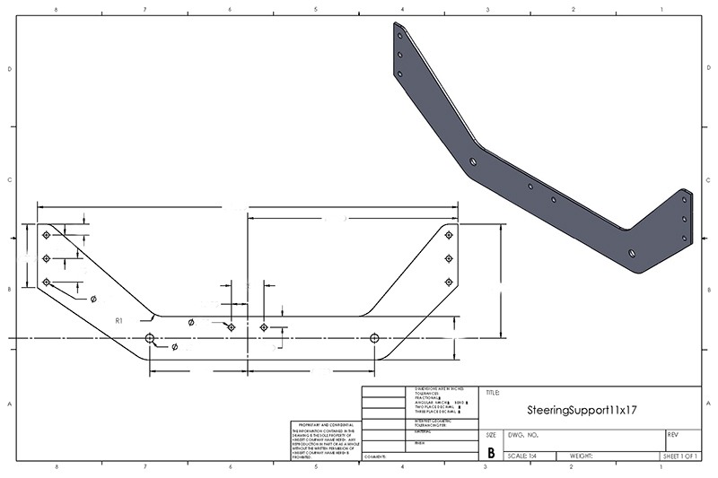
 0
0 -
Ta Daaa.....! Yep, I now have the R & P unit installed sans all of the construction and alignment supports that were needed in the beginning. I made 3 other smaller mounting brackets that the large horizontal bracket is attached to. Two of the brackets are welded to the outer frame rails (one on each side) The center bracket is welded to the lower frame yoke which in turn bolts to the center of the horizontal bracket. This center bracket can't be seen in this photo. By doing this it forms 2 triangles which adds strength for handling the strong lateral forces needed when turning the car. By building it this way, I can remove parts when I need to for upgrades or repairs.
Peace,
Chaz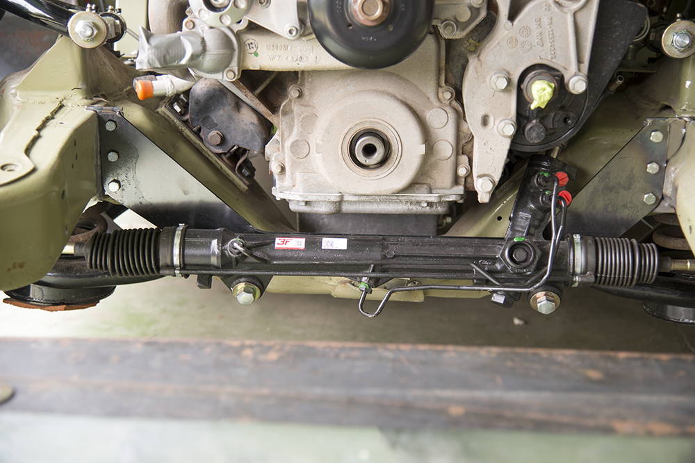
0 -
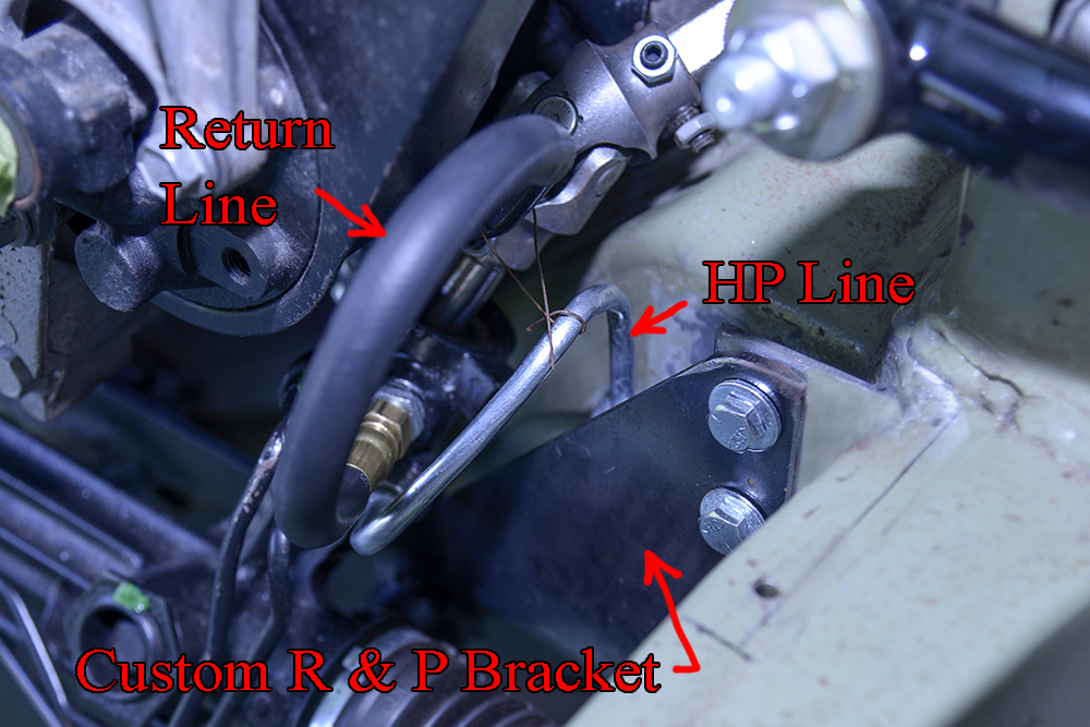
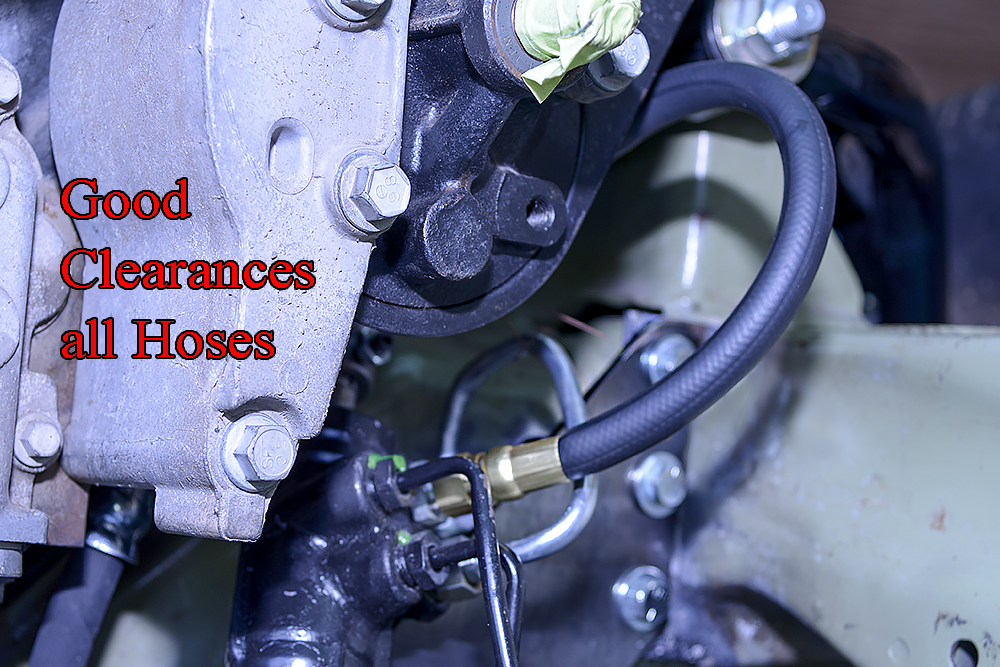
Sorry guys that it's taken so long to get back to the Hudson. My time has been spent writing and illustrating of 2 children's stories which has been my top priority these days. That's business before pleasure as you know! Anyway, here is an update on finishing and installing the PS hoses which means I can go on to other projects on the car. Like I always do, I make patterns first before committing to the end product.
I need to give a big thank you to Hydraulic Specialists in San Antonio for their help making my hose connections. Good people to work with!
Peace,
Chaz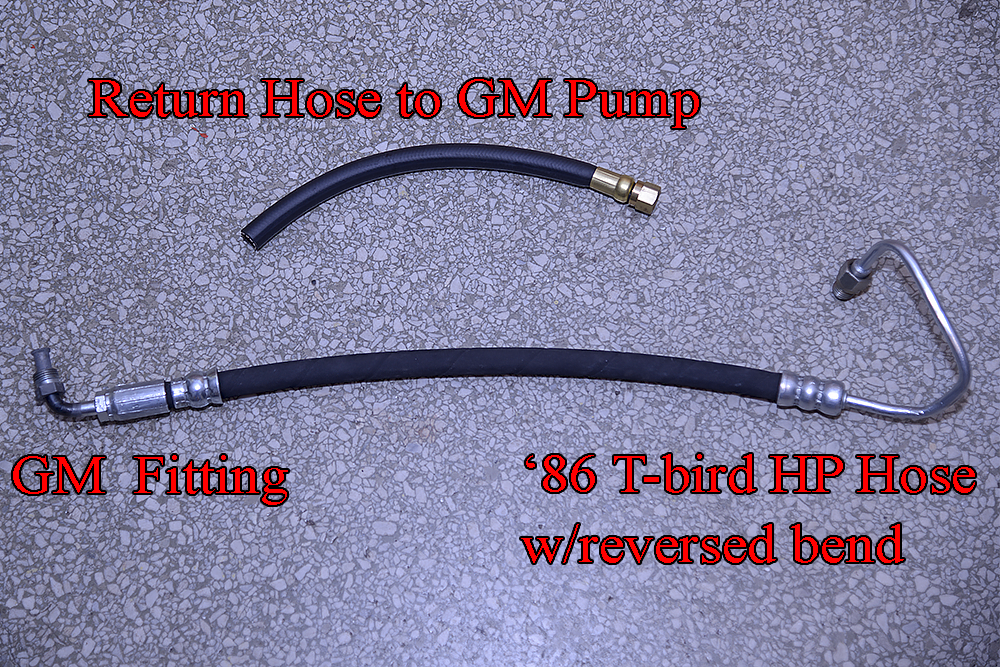
0 -
this forum needs a like post feature.

0 -
I agree KK.
0 -
Great work indeed.
0
Categories
- 37K All Categories
- 115 Hudson 1916 - 1929
- 21 Upcoming Events
- 94 Essex Super 6
- 28.6K HUDSON
- 576 "How To" - Skills, mechanical and other wise
- 995 Street Rods
- 151 American Motors
- 180 The Flathead Forum
- 49 Manuals, etc,.
- 78 Hudson 8
- 44 FORUM - Instructions and Tips on using the forum
- 2.8K CLASSIFIEDS
- 609 Vehicles
- 2.2K Parts & Pieces
- 77 Literature & Memorabilia
- Hudson 1916 - 1929 Yahoo Groups Archived Photos

 Have you seen the Flaming River Camaro kit?
