My gear shifting problem has returned
Old Fogey UK
Expert Adviser
in HUDSON
I thought I'd solved this problem after I took Geoff's advice and adjusted the clutch pedal travel to 3/4 inch movement before the pedal begins to bite.
However I took the 34 out yesterday for the first long run after the engine overhaul. After an hour of driving, it got hard to shift the gears and by the time I got home it was almost impossible. Even with the clutch pedal right to the floor it felt like it wasn't moving far enough.
Got the car out this morning and there was no problem shifting with a cold engine.
So looks like it's got something to do with heat.
It's a mystery to me - what's going wrong ?
Please can anyone help with some advice ?
Thanks,
David.
0
Comments
-
I had that issue once with my 46 pickup with a new clutch. The clutch disk was swelling up when the engine got heated up. one of the other symptoms was that the clutch wasn't releasing all the way. Are you experiencing that as well? My clutch was too thick.0
-
Yes I am.54coupe said:I had that issue once with my 46 pickup with a new clutch. The clutch disk was swelling up when the engine got heated up. one of the other symptoms was that the clutch wasn't releasing all the way. Are you experiencing that as well? My clutch was too thick.
My clutch disk came from Wildrick so I had assumed it was OK.
How did you cure the problem ?
I think long term I'm going to replace it with a Kevlar lined disk but as I have just got the car back on the road after a 4 month overhaul, I would like to get a summer's worth of driving before getting into that.0 -
I ended up taking it apart and putting it back together with two gaskets instead of one. This was a common problem back in the 70's (when this happened), with the clutch discs that Clifford sold.0
-
How much free play does the pedal have? There should be 1". If less that that the clutch may be slipping slighlty, causing heat build-up. How thick is the gasket between the pressure plate and flywheel? It should be .030" minimum.0
-
In addition to Geoff's comment I wonder what a min and max specification would be for the cork disc? I have just miked 3 discs I had laying around - two used and one new - I would have to guess any and all would have worked although I have no history on any of them. There are 3 rows of corks - an outer, middle and inner. My miocrometer can only reach the first and second row and I only did a random measurement and tried to average a repeating (mean?) thickness. First I was amazed at how constant the thickness was from disc to disc - of course no telling if the steel plate is warped. So the new one measured about .157-164 with the latter number my average guesstimate. Next a used plate that looked worn and overly dry was surprisingly .184-.190 with .184 my average. Third used plate looked good and was ,154-.180 with about .170 average. Gert0
-
The specs are .185 to .210" total thickness, but of equal importance is the condition of the throw-out fingers, the thickness of the gasket, and the fingers on the throw-out fork that sits in the t/o bearing cage. Also the condition of the pins holding the lever on the end of the shaft. I did a clutch some years ago, that I used too thin a gasket, and I cut a new thicker one, undid all the bolts, cut the new gasket diametrically, and wound it inot place, using a good sealant at the join. Did it all up again. No more problems.0
-
Pedal travel is about 3/4 inch, Geoff, as you recommended.
I still have my original clutch disc in the garage but the corks look pretty flat and dried up.
I have a car show to go to this weekend ( just a mile from home ) but next week I think I may pull out the gearbox and clutch and have a look-see with my Rolls Royce trained friend.
If I can discover the specifications of the Kevlar lining, I'll use my spare disc as a donor for
relining . Anyone know what they are, please ?0 -
And in case you ask, Geoff, it is raining here - and it's forecast for the whole weekend !0
-
Have you checked that the linkage is engaged in the hole nearest the pivot of the throw-out mechanism? If it is in the outside hole it reduces the movement.0
-
Old Fogey UK said:Pedal travel is about 3/4 inch, Geoff, as you recommended.
I still have my original clutch disc in the garage but the corks look pretty flat and dried up.
I have a car show to go to this weekend ( just a mile from home ) but next week I think I may pull out the gearbox and clutch and have a look-see with my Rolls Royce trained friend.
If I can discover the specifications of the Kevlar lining, I'll use my spare disc as a donor for
relining . Anyone know what they are, please ?Old Fogey UK said:Pedal travel is about 3/4 inch, Geoff, as you recommended.
I still have my original clutch disc in the garage but the corks look pretty flat and dried up.
I have a car show to go to this weekend ( just a mile from home ) but next week I think I may pull out the gearbox and clutch and have a look-see with my Rolls Royce trained friend.
If I can discover the specifications of the Kevlar lining, I'll use my spare disc as a donor for
relining . Anyone know what they are, please ?
Same as the cork thickness .218, just on a side note What fluid are you using.?? If ATF some brand oils boil quicker than others, we use Dexron 111 also what thickness gasket did you use between the flywheel and pressure plate.???Old Fogey UK said:Pedal travel is about 3/4 inch, Geoff, as you recommended.
I still have my original clutch disc in the garage but the corks look pretty flat and dried up.
I have a car show to go to this weekend ( just a mile from home ) but next week I think I may pull out the gearbox and clutch and have a look-see with my Rolls Royce trained friend.
If I can discover the specifications of the Kevlar lining, I'll use my spare disc as a donor for
relining . Anyone know what they are, please ?0 -
Thanks for the advice so far, the corks theory sounds very believable.
I don't know how thick a gasket was used because it was installed by the original engine
rebuilder.
I'm using Dexron III.
I'm using the outer hole in the pivot arm. I 'll try the inner hole.
Otherwise it's the gearbox and clutch out next week.
I'll post about what I find out inside.0 -
Willing to wager using the inner hole fixes the problem!
0 -
Agree with Geoff. I’ll check my ‘34 linkage but I’m fairly certain it’s set using the inner hole. If you find you have to pull the trans, make sure to clean out the ball detents in the top front of the trans housing and re-grease them well. Also check the shift linkage on the side of the trans housing for proper setup as well0
-
I have 3 holes in the pivot arm.
Up to now , I've used the outer hole adjusted to get about 3/4 inch play on the clutch pedal.
Today I tried the inner hole and had play almost to the floor no matter how I adjusted it.
So I used the middle hole that I could adjust up to 1 1/2 inches of play.
Enormous graunching sounds trying to select any gear on start up.
So it looks like only the outer hole is going to work for me - at least before completing a long run.
Any more thoughts ?0 -
Before doing any drastic dismantling of my transmission, I would like to check that my clutch interlock mechanism has been properly installed.
Although the car is a 1934, it has been retrofitted with the 1935-6 interlock.
Please could an owner of a '35 or '36 car post a close up pic of their interlock ?
That would be a terrific help to me.
Thanks.
David.0 -
I'm perplexed! Moving to the inner hole will impart greater movement to the shaft, unless there is some basic change has occurred to the linkages. Look at page 5 of section 8, figure 805 of the workshop manual. Are you moving the the clevis C to the inner hole of the lever?0
-
Or have you moved the top clevis to the inner hole of the pedal?0
-
I don't understand what you mean here, Geoff.Geoff said:Or have you moved the top clevis to the inner hole of the pedal?
Tomorrow, I'll take the floor out and take some pics to show what the set up is like.0 -
I have had another go and managed to set the pedal at an inch of play using the middle hole.
I can now select gears without crunching when the motor is running.
Road test tomorrow.0 -
Sorry, I'm mixing my metaphors, the '29 Essex had two holes in the pedal lever., which made a difference to the movement imparted. your H8 has only one. I still think you could use the inner hole though.Old Fogey UK said:
I don't understand what you mean here, Geoff.Geoff said:Or have you moved the top clevis to the inner hole of the pedal?
Tomorrow, I'll take the floor out and take some pics to show what the set up is like.0 -
The pivoting arm that is secured to the yoke on my car has 3 holes. I set it in the outermost hole relying on some photos of the linkage assembly on Jim DiGiorgio's 1934 car, because that was how Jim had done it.Geoff said:
Sorry, I'm mixing my metaphors, the '29 Essex had two holes in the pedal lever., which made a difference to the movement imparted. your H8 has only one. I still think you could use the inner hole though.Old Fogey UK said:
I don't understand what you mean here, Geoff.Geoff said:Or have you moved the top clevis to the inner hole of the pedal?
Tomorrow, I'll take the floor out and take some pics to show what the set up is like.
The ROC repair manual only has a crude diagram of how the yoke and arm go together but, interestingly, that shows the yoke seemingly attached to the middle hole.
You can't tell which hole in the arm is used from the illustration in the Hudson Mechanical Procedure Manual.
I can shift gears with the clevis pin through the middle hole with a cold motor. A long road run will show if I still can do this with a hot motor. That's scheduled for tomorrow.
Attaching the yoke and clevis pin to the innermost hole wouldn't allow me to select a gear at all, even with the engine turned off.0 -
Oaky, that will be because the interlock is in a different position, because it has been moved further. Leave it in the inner hole, get some one to hold the pedal in, and check that the interlock is not blocking the detent pin from moving. You will probably have to lower it slightly by adjusting the lifting link. Good luck.0
-
Geoff, does that mean you want me to use the inner hole not the middle one I've now used to set the pedal ?Geoff said:Oaky, that will be because the interlock is in a different position, because it has been moved further. Leave it in the inner hole, get some one to hold the pedal in, and check that the interlock is not blocking the detent pin from moving. You will probably have to lower it slightly by adjusting the lifting link. Good luck.
The interlock is working OK at the moment and I have about an inch of play at the pedal before resistance starts.
Before changing to the inner hole, I'll do a test run tomorrow to see if the middle hole setup cures the gear shifting problem I've been getting when the engine is totally warmed up.
However, I'd still really appreciate it if someone could please send me a close up pic of a '35 or '36 installed interlock to make sure I've assembled it correctly.0 -
Can't send you a pic, but the interlocks should be sitting right down with the clutch pedal up. When the pedal is depressed the interlock slides should be lifted up so that the pins of the detents are able to move out. If you have a workshop manual there is a picture on page 3 Section 10, fig 1002.0
-
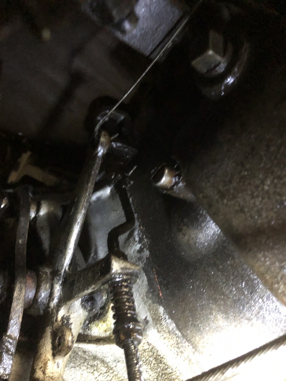
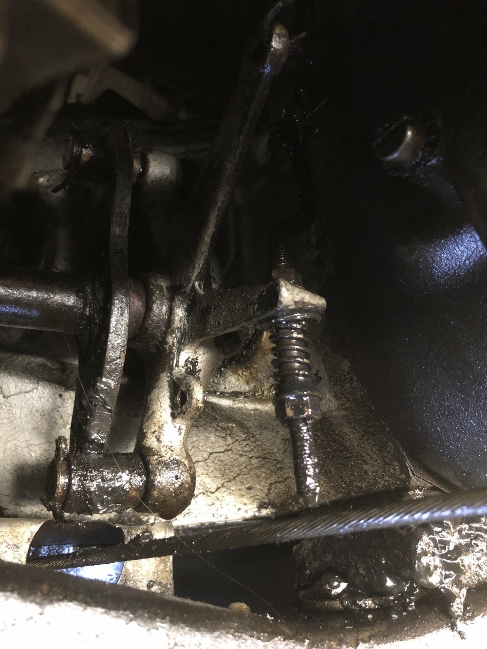
This is my interlock.
It works OK but I'm not sure if it's correctly installed.0 -
Just brought my 35 home from the storage garage. Will take some pix tonight. Can't remember, do you have a 6 cyl or eight cyl.0
-
It's an Eight.
Thank you.0 -
Yours is cleaner than mine
 0
0 -
And I’m in the first hole
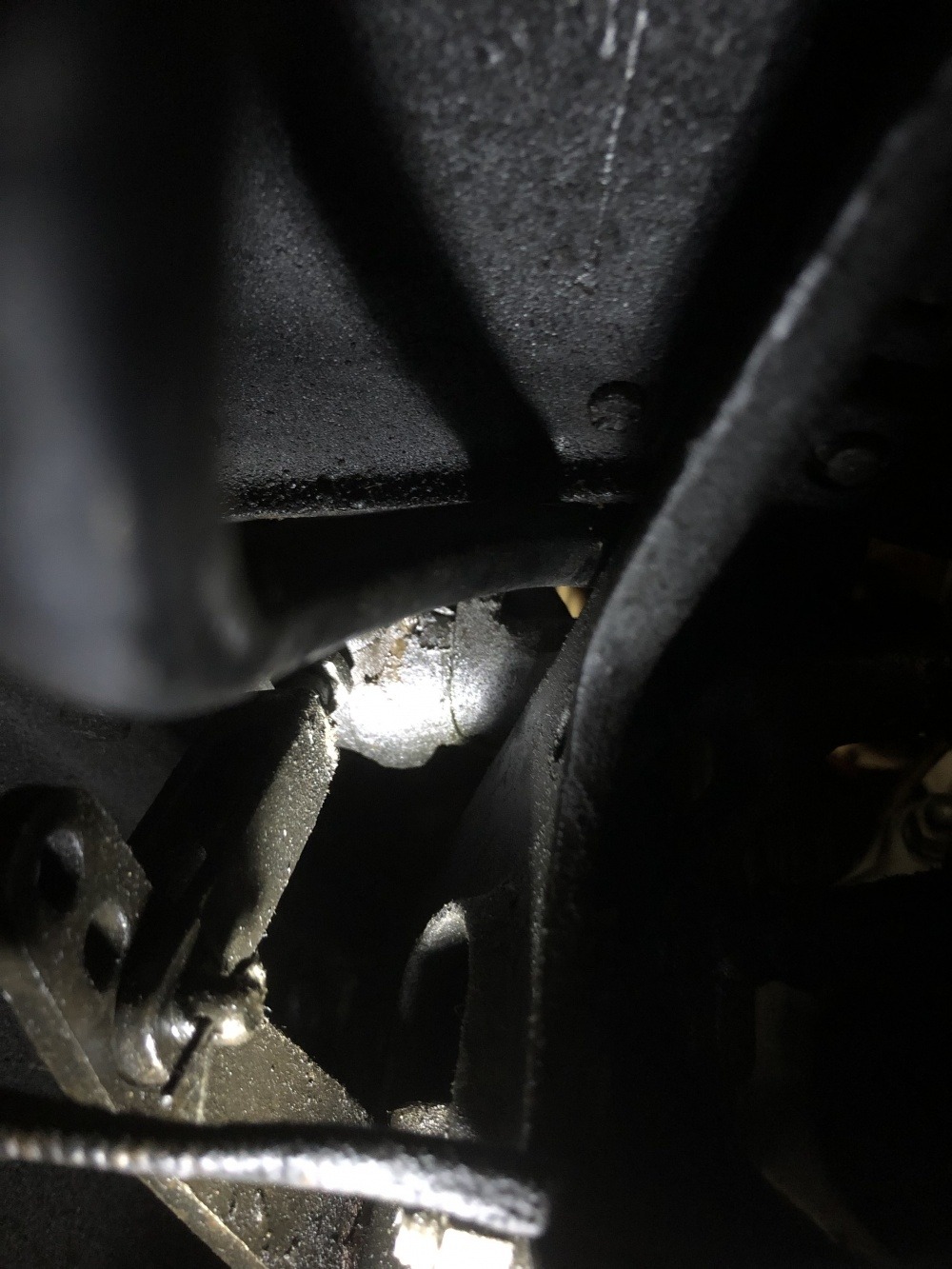 0
0 -
Thank you very much for these pics.
It's comforting to know I put it together properly !
I'm taking the car out this morning to see how things go using the middle hole.
My interlock normally looks no more clean than yours - I wiped it off specially for taking pics !?0
Categories
- 37K All Categories
- 104 Hudson 1916 - 1929
- 19 Upcoming Events
- 91 Essex Super 6
- 28.6K HUDSON
- 559 "How To" - Skills, mechanical and other wise
- 993 Street Rods
- 150 American Motors
- 173 The Flathead Forum
- 49 Manuals, etc,.
- 78 Hudson 8
- 44 FORUM - Instructions and Tips on using the forum
- 2.8K CLASSIFIEDS
- 599 Vehicles
- 2.1K Parts & Pieces
- 77 Literature & Memorabilia
- Hudson 1916 - 1929 Yahoo Groups Archived Photos
