1933 Terraplane rear body panels
bent metal
Senior Contributor
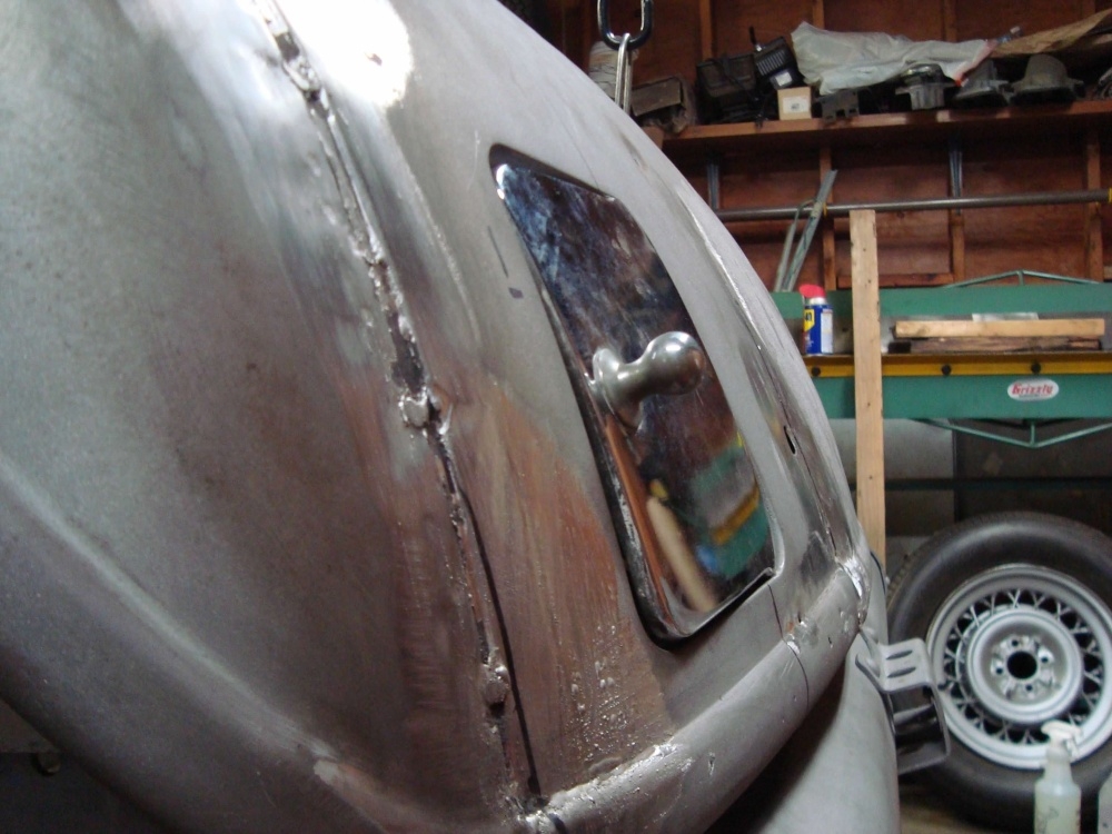
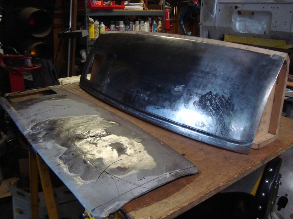
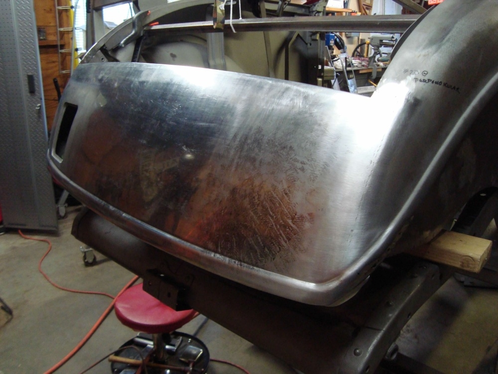
This car had been hit in the rear at some time and poorly repaired. The panel I was working on was just below the rumble seat lid. It didn't look too bad at first. But the lead was failing in a few spots. So once I stipped off some of the lead I could tell this panel was going to need to be re-made. The contours of the panel are pretty important here. So I made a buck that was the same shape as the panel I needed.


0
Comments
-
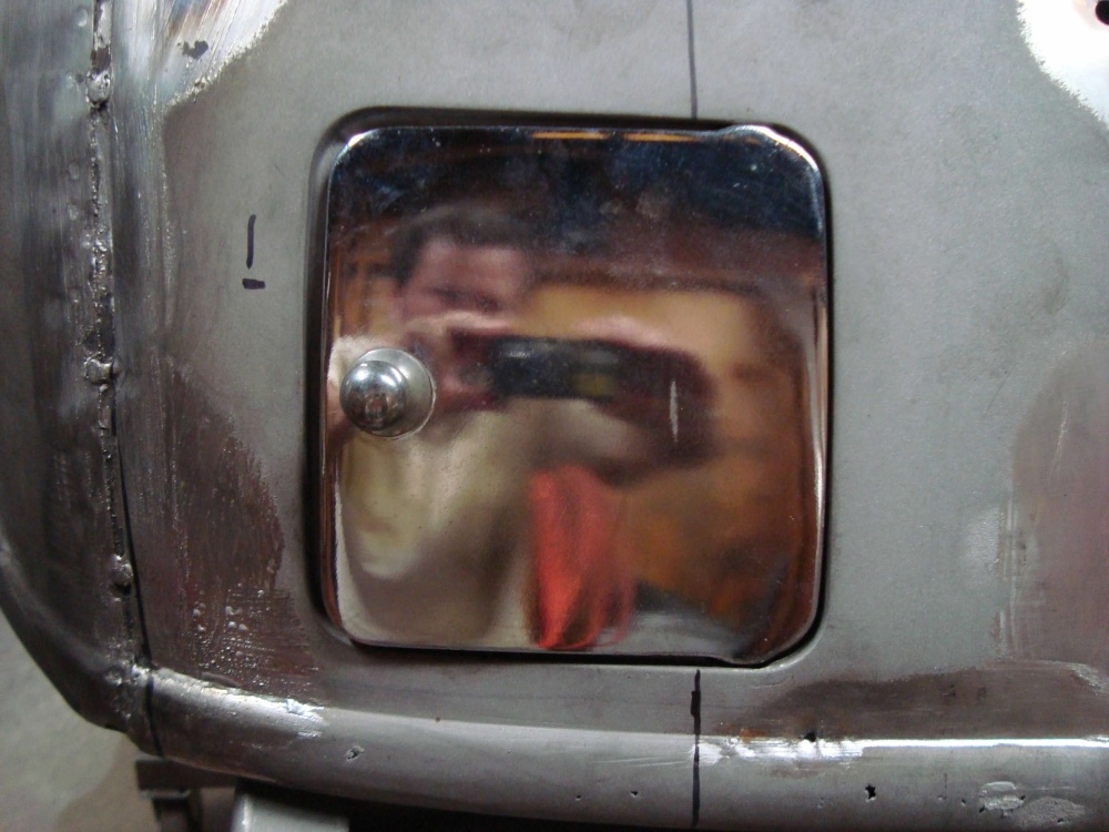
I figured while I was making this piece I might as well make it a little wider, thus eliminating the factory lead seam. The gas door and the flange around the gas door looked good and would be time consuming to re-make. So I decided to cut it out and weld it into the new panel.
0 -
Love watching your work. Awesome0
-
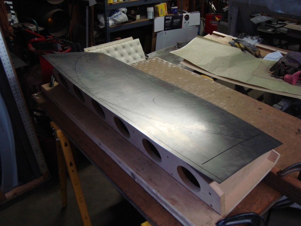
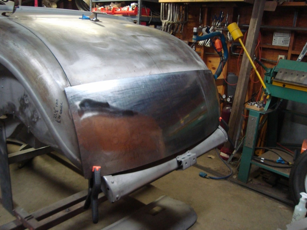
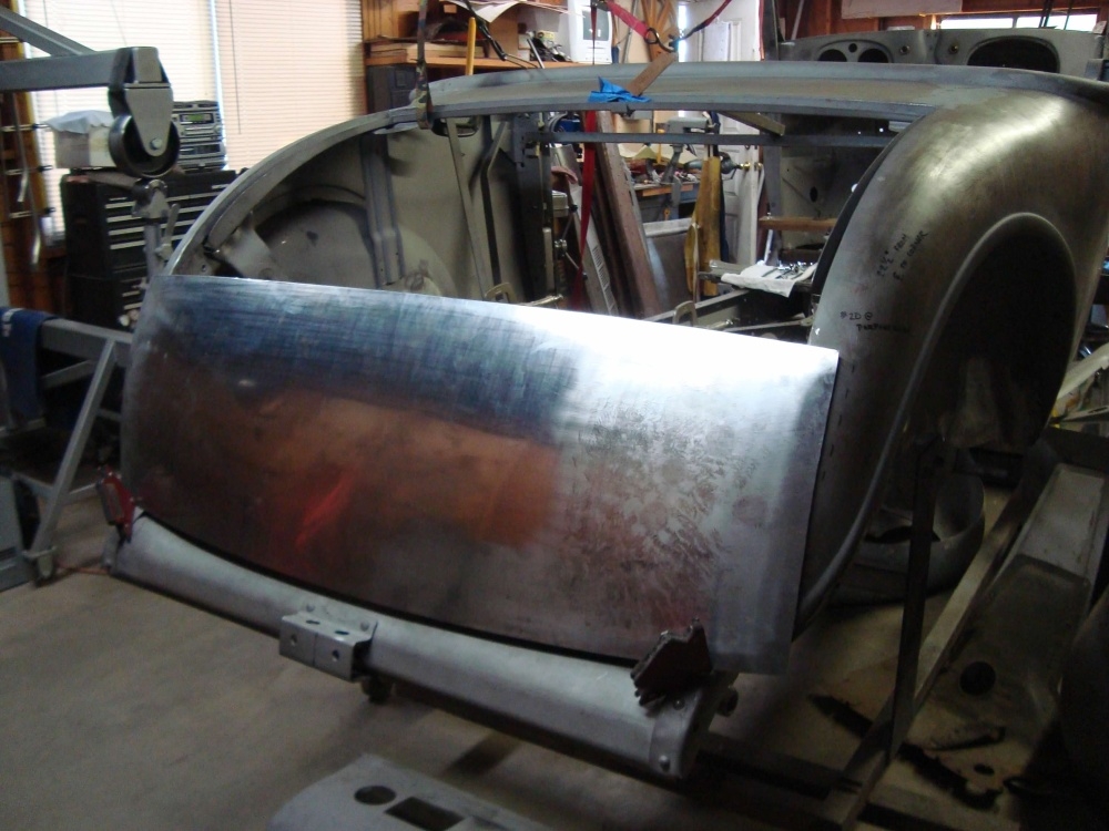
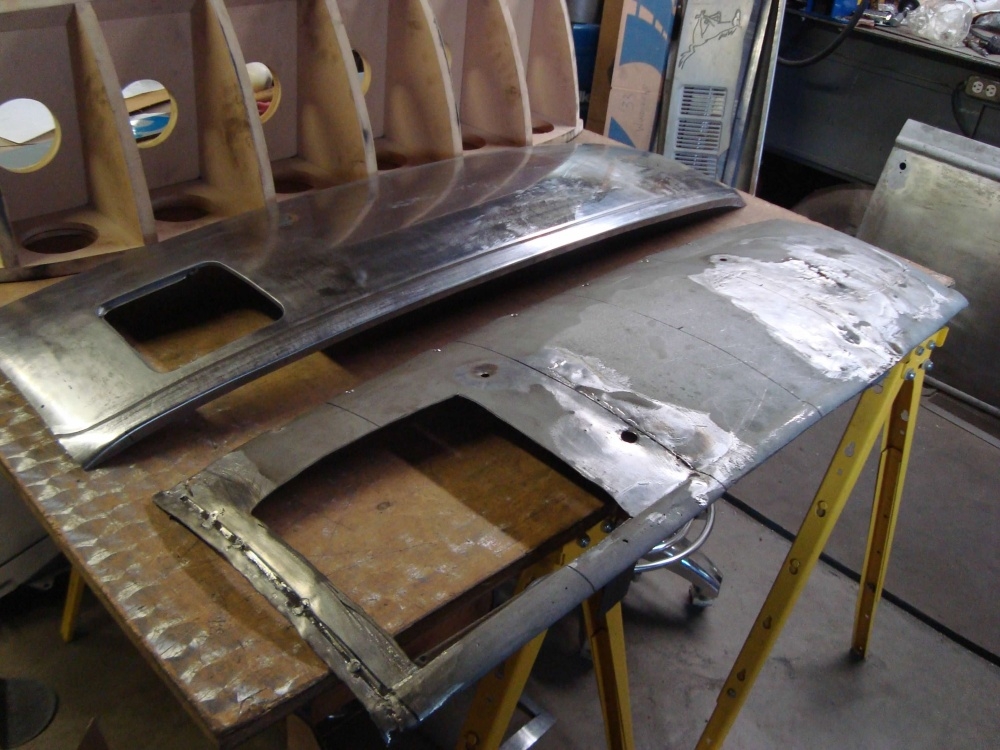
This body panel has a lot of shape in it, and more so across the bottom. The upper flange needs to be within' pretty tight clearance of the rumble seat. The bottom edge has a bead detail that needs to line up with the fenders. I English wheeled this panel to shape and made it a little over sized so I could trim to fit later.
 0
0 -
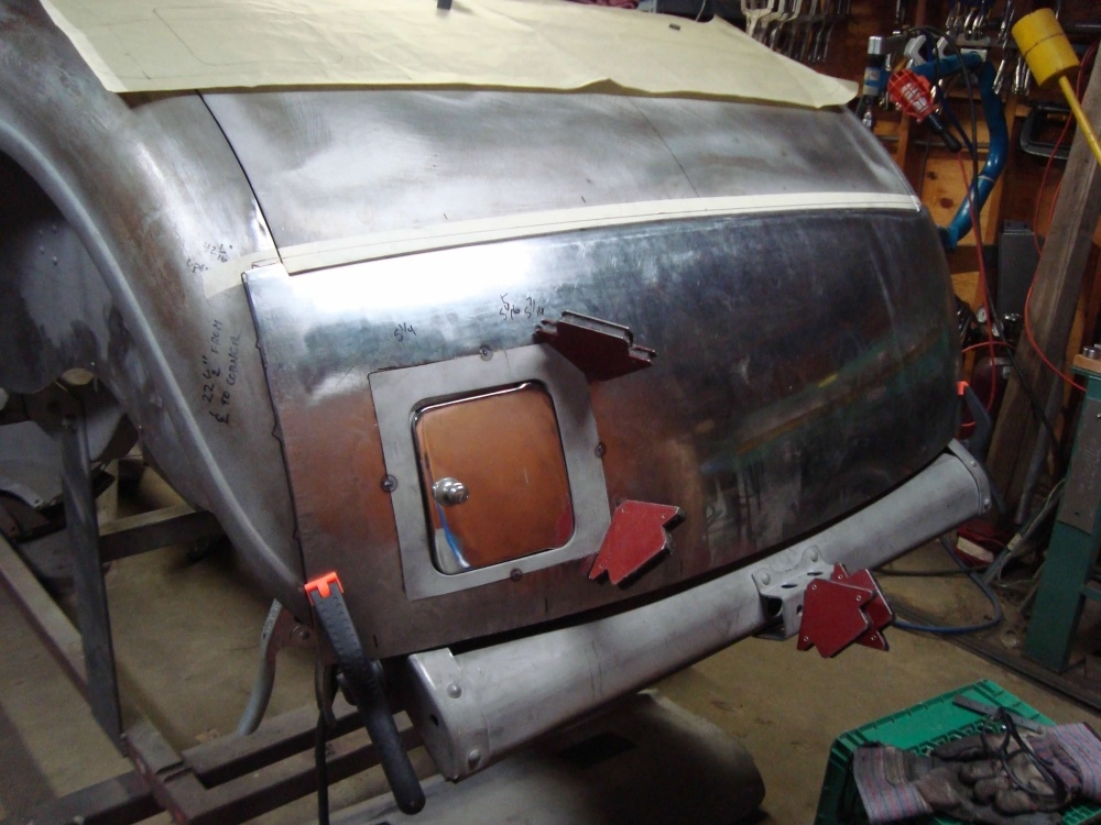
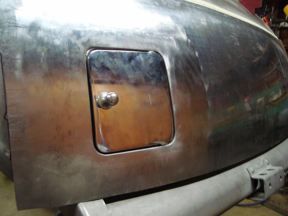
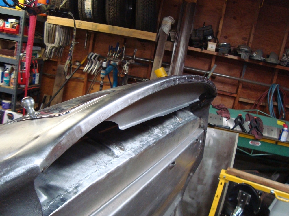
The gas door was then welded in. The flange across the top and the bead across the bottom was installed.
0 -
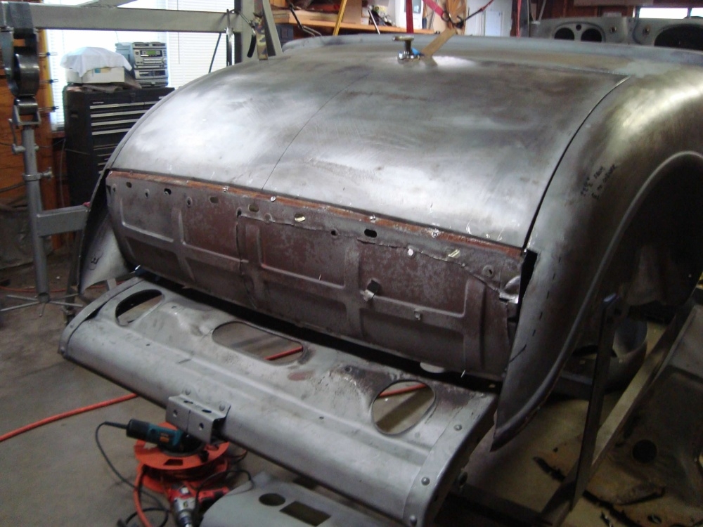
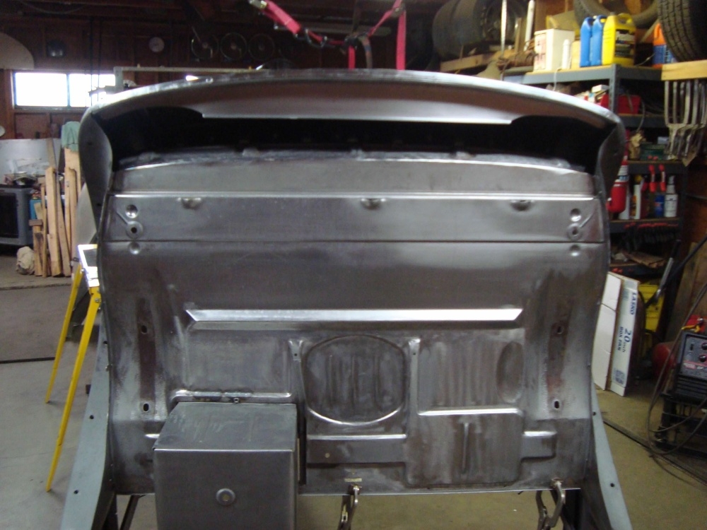
A little surprise under the body work. ANOTHER screwed up piece of sheet metal to fix!
 Haha. After talking with the owner, we decided the inner structure was structurally sound but needed straightened up, welded, cleaned up. It didn't need to be replaced. I forgot to take a picture of it "after" it was repaired. But, there you get to see what the inside looks like.
0 -
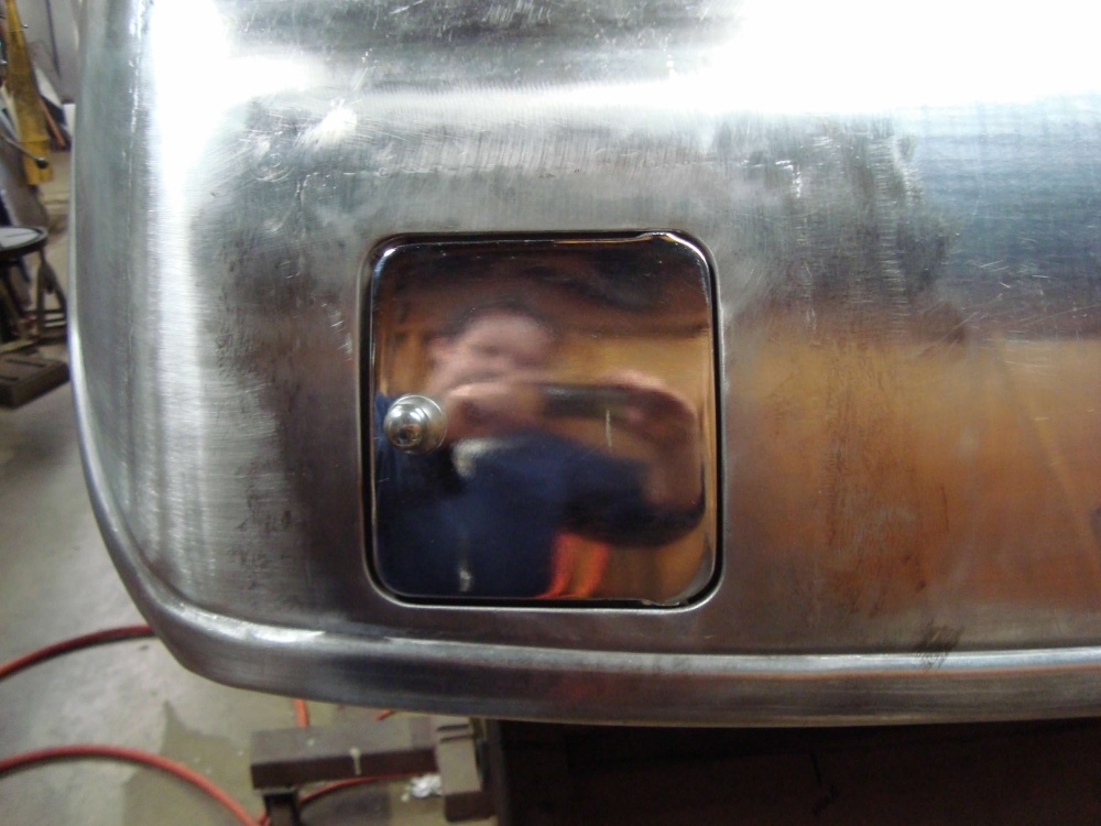
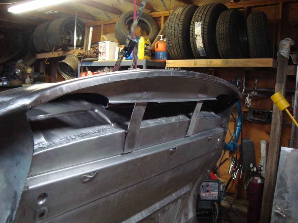
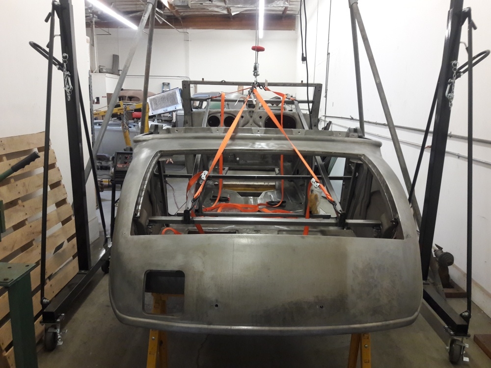
The new panel welded on the car. Notice that the new panel extends past the original factory lead seam where it meets the fenders, thus eliminating the lead seam. I also added the factory inner structure that goes underneath. There is also a sneak peak at the floor, which needed to be made also. More on that later.
0 -
0 -
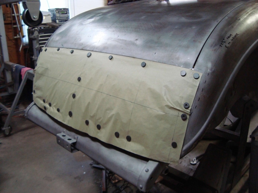
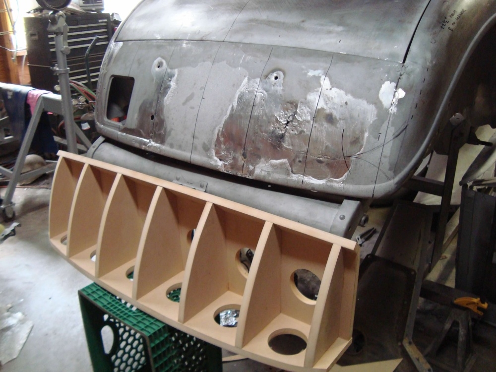
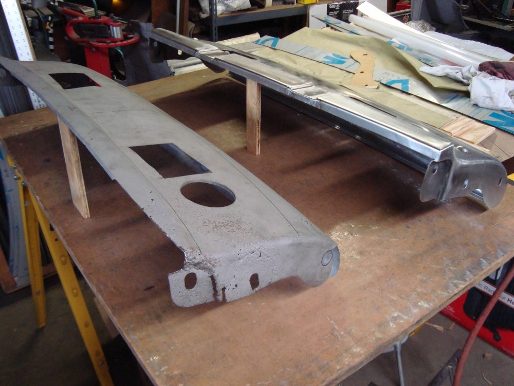
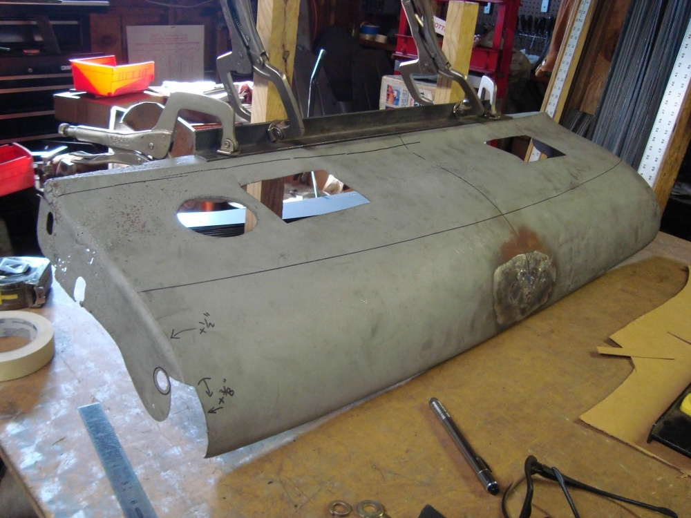
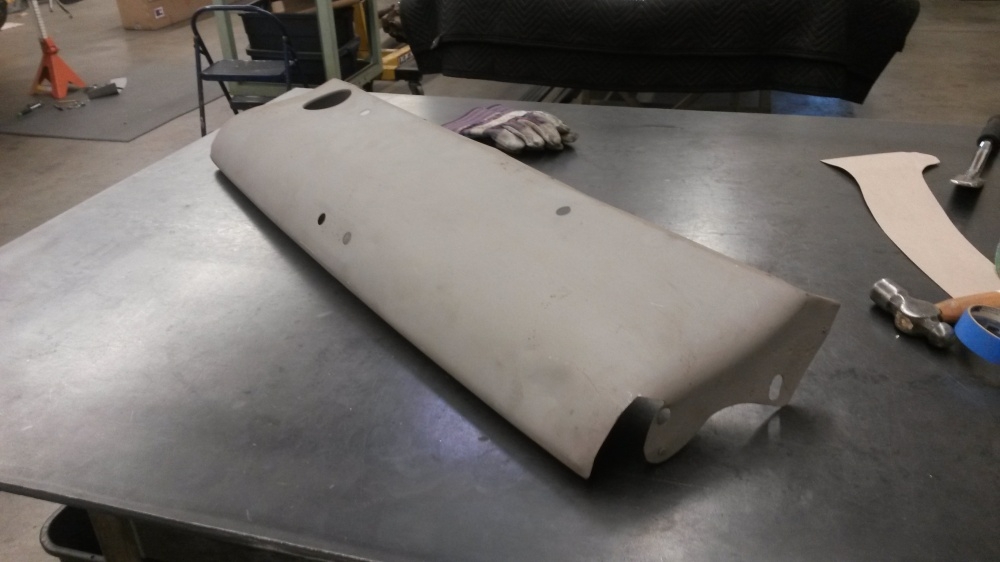
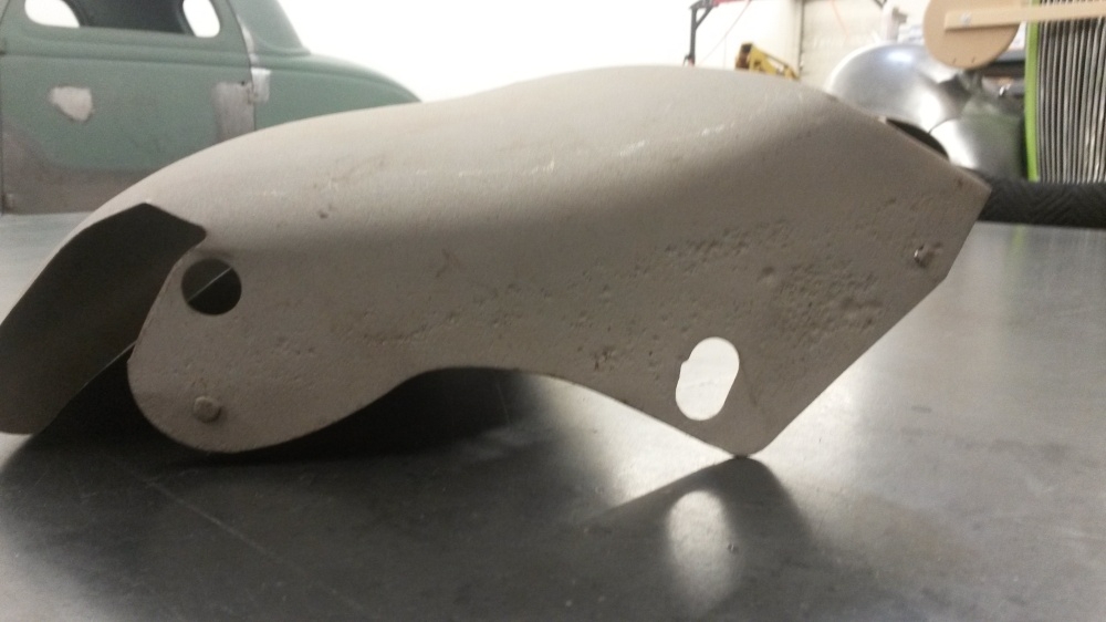
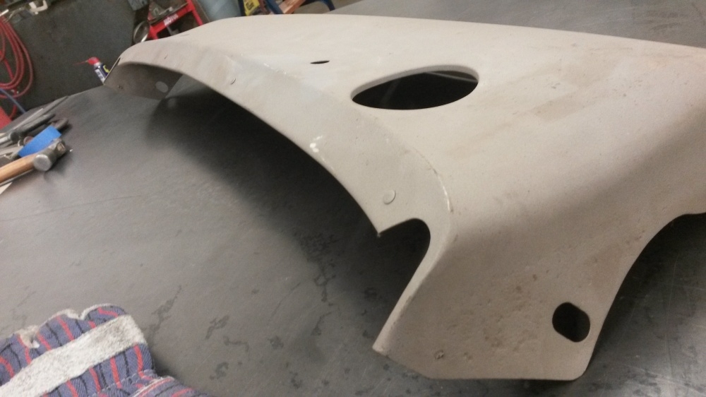
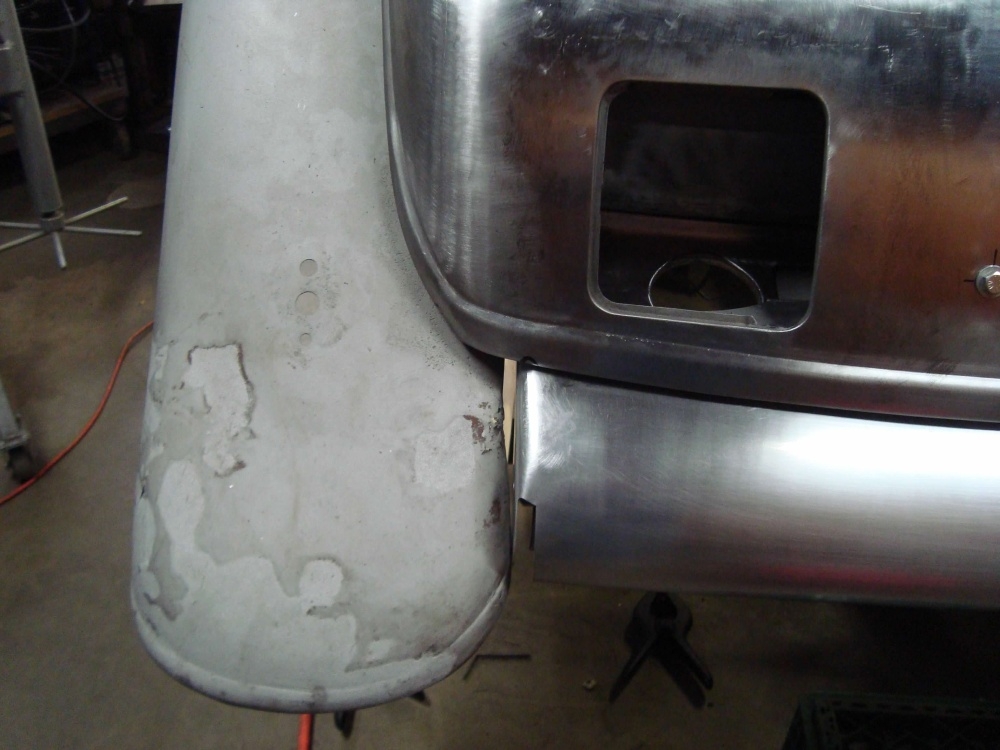
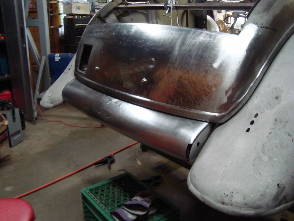
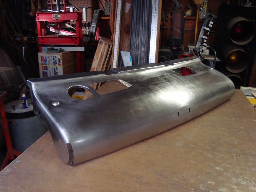
Under the body, across the back is a frame cover. We had one, but it was rough. After asking around, we got a replacement. But it turned out to be wrong. I think it was for a sedan body. So,...I gotta' make one.
 0
0 -
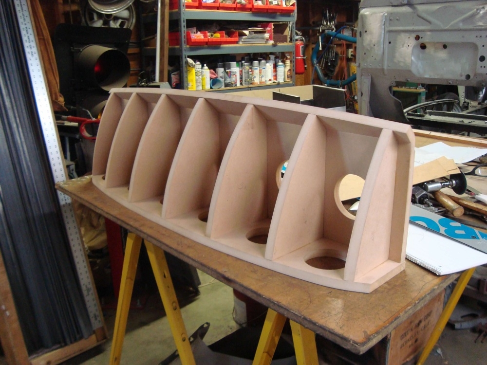
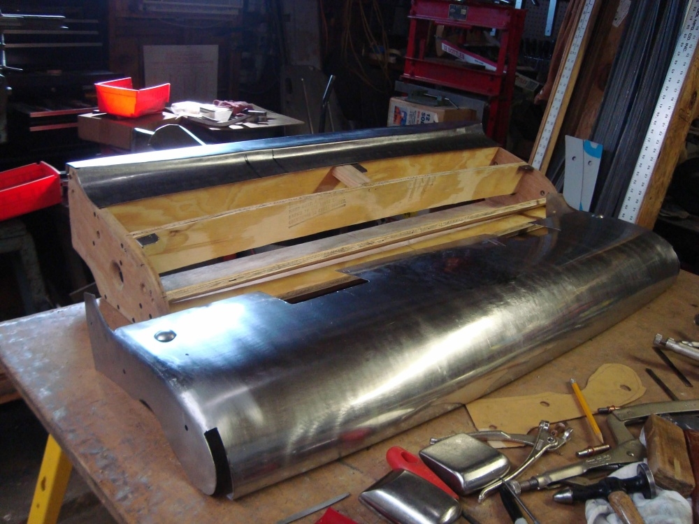
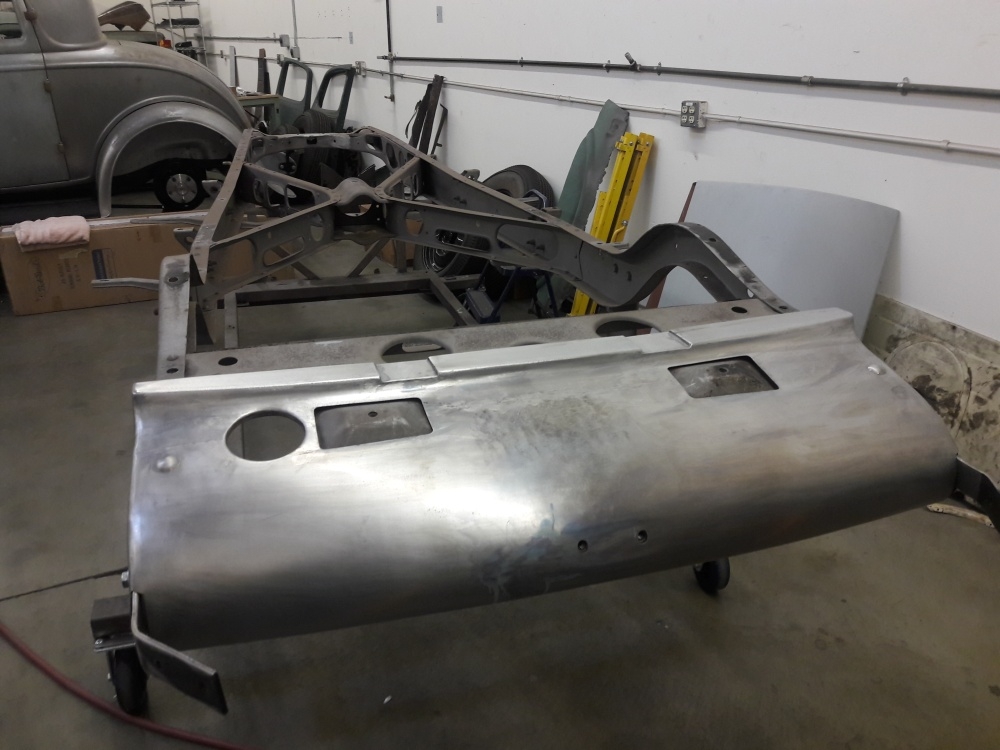
Complicated little part that needs to fit tight in certain areas. I'll need to make a buck in order to make the part accurately. This panel needs to go around the frame sides so that the bumper brackets can attach to the frame sides. Then also bolt to the frame up under the body.
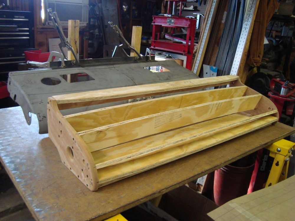
0 -
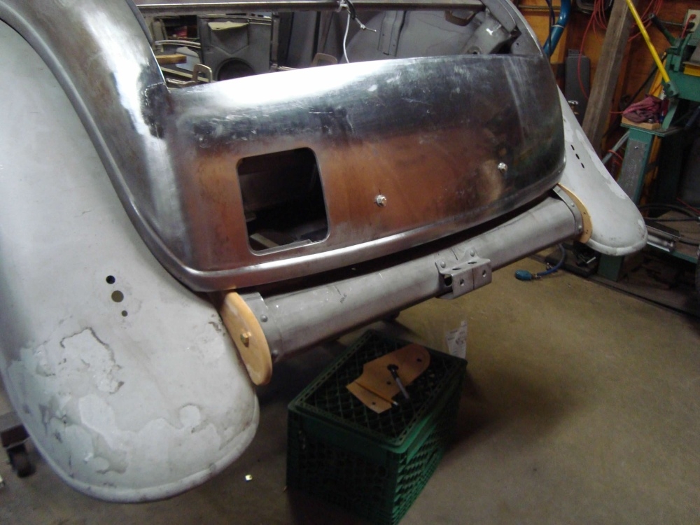
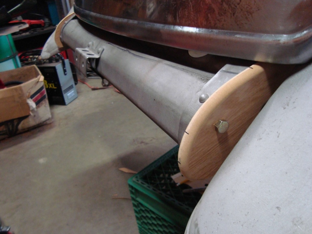
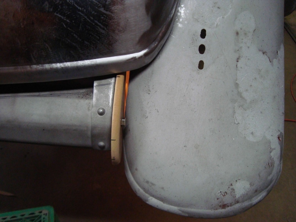
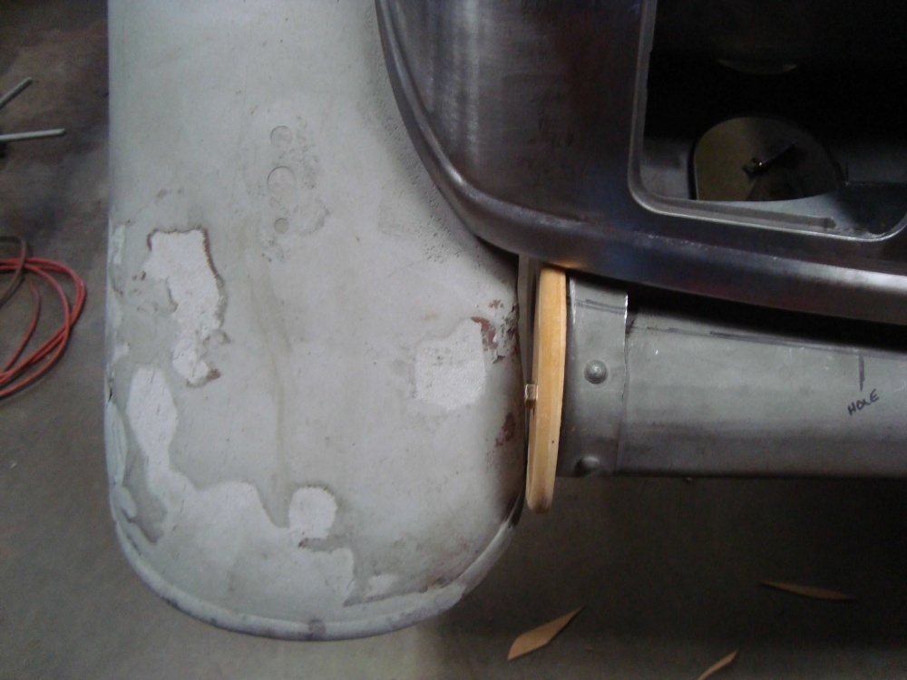
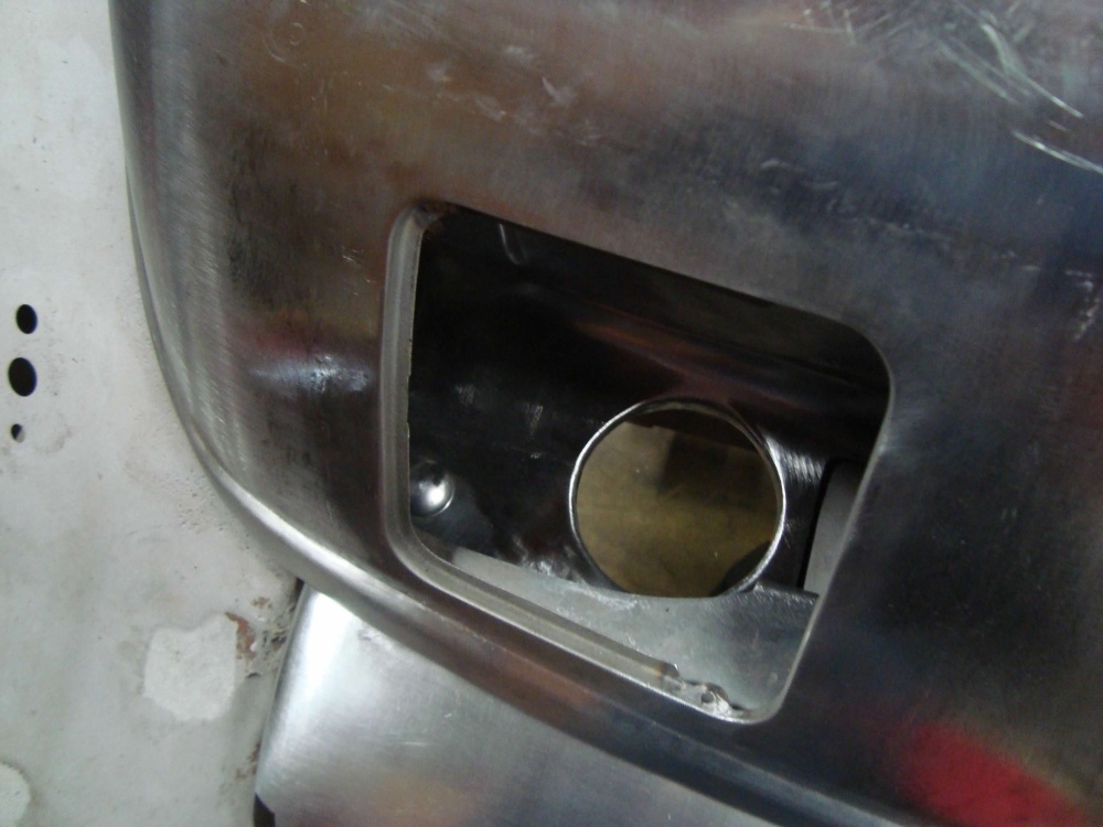
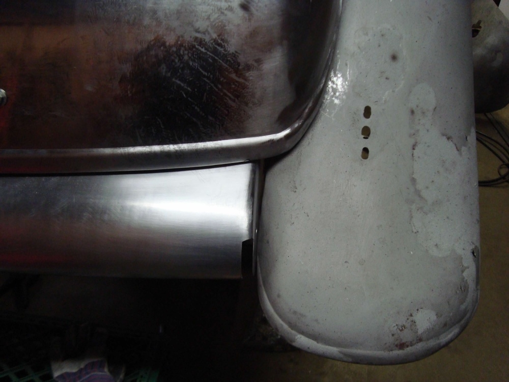
This piece has slots at both ends to allow the bumper brackets to pass through and bolt to the side of the frame.
 0
0 -
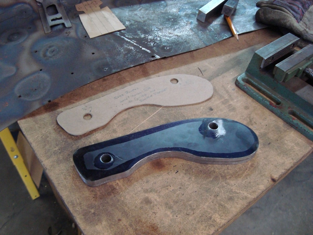
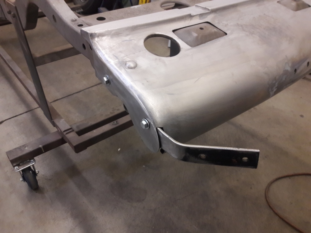
Mounted on the chassis. One thing I noticed when looking at other cars like this one, is that the bumper brackets didn't look centered in the body panel slot. The bumper brackets were either crowded to the inside, or outside, and on some of the cars the bolts for the bumper brackets had distorted the sheet metal where the bolt passes through. So I made these shims. Four in total. A shim to go on both sides of the bumper bracket, on both sides. This would both center the bumper bracket in the slot opening, and support the sheet metal sides where the bumper mounting bolts pass through. I made the shims the same shape as the sheet metal sides of the frame cover so when looking from underneath there is no unsightly gaps in there. If you look at these pictures below you might find it interesting that when mounting the body, this rear frame cover has to go on first. With the body, on the rear frame cover will not go on or come off.
0 -
This is just stunning.Regards, Tom0
-
Thank you, glad you are enjoying the photos.
 0
0 -
Wow. Great work.0
-
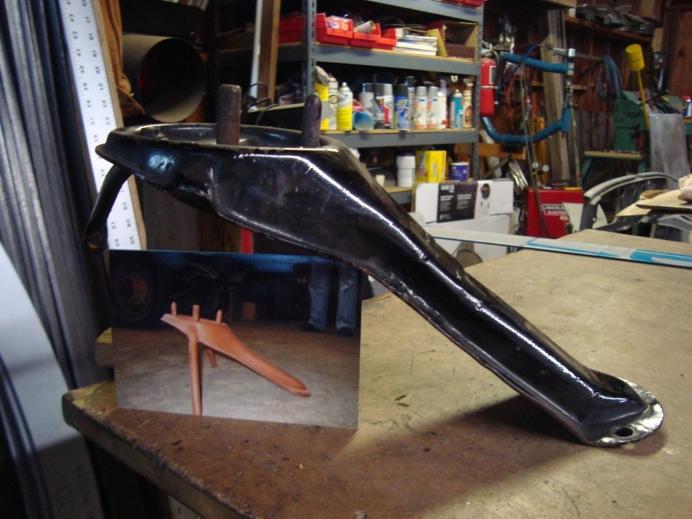
Now that the rear sheet metal is squared away, it's time for the spare tire mount. We had a hard time finding the right one. Sedans are different then coupes etc.. We had a few different variations, none were right, and only pictures of the correct configuration spare tire bracket.
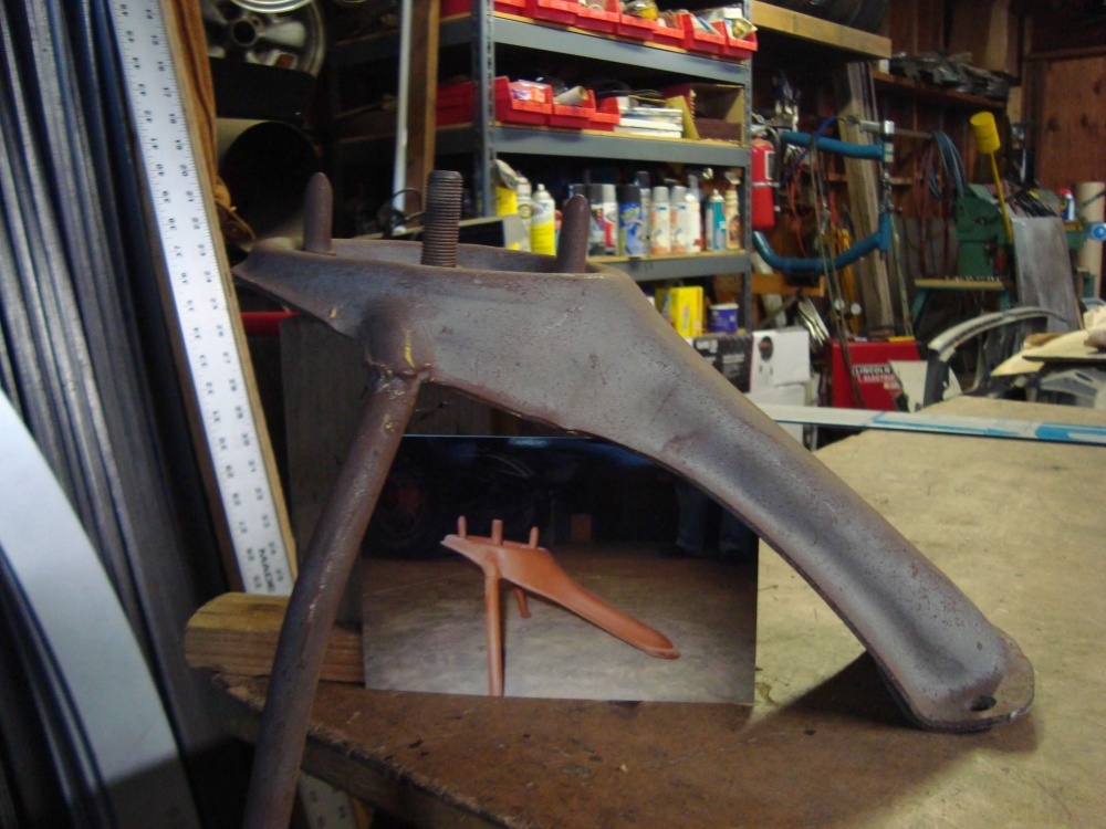
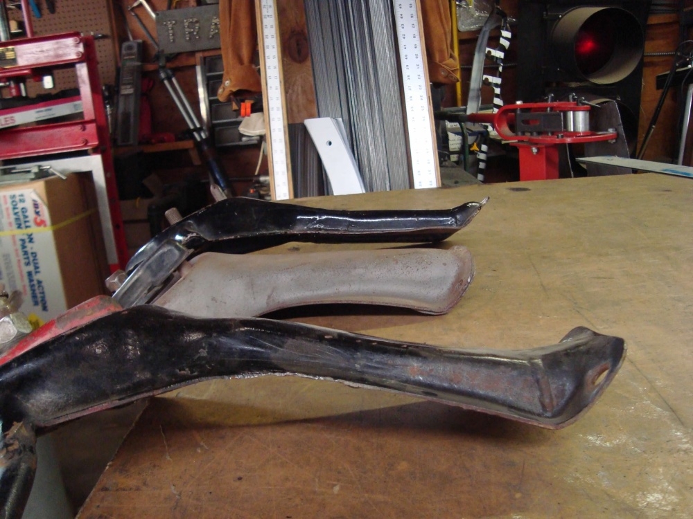
0 -
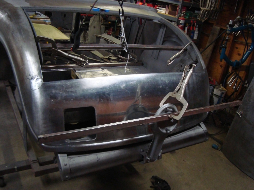
I cut the top off of one, the bottom off another, then made whatever was missing. After I had the main part of the bracket established, I clamped some square tubing to the tire mounting surface then measured from the front of the car to the ends of the square tubing to make sure the new bracket was going to hold the tire square and straight with the body.
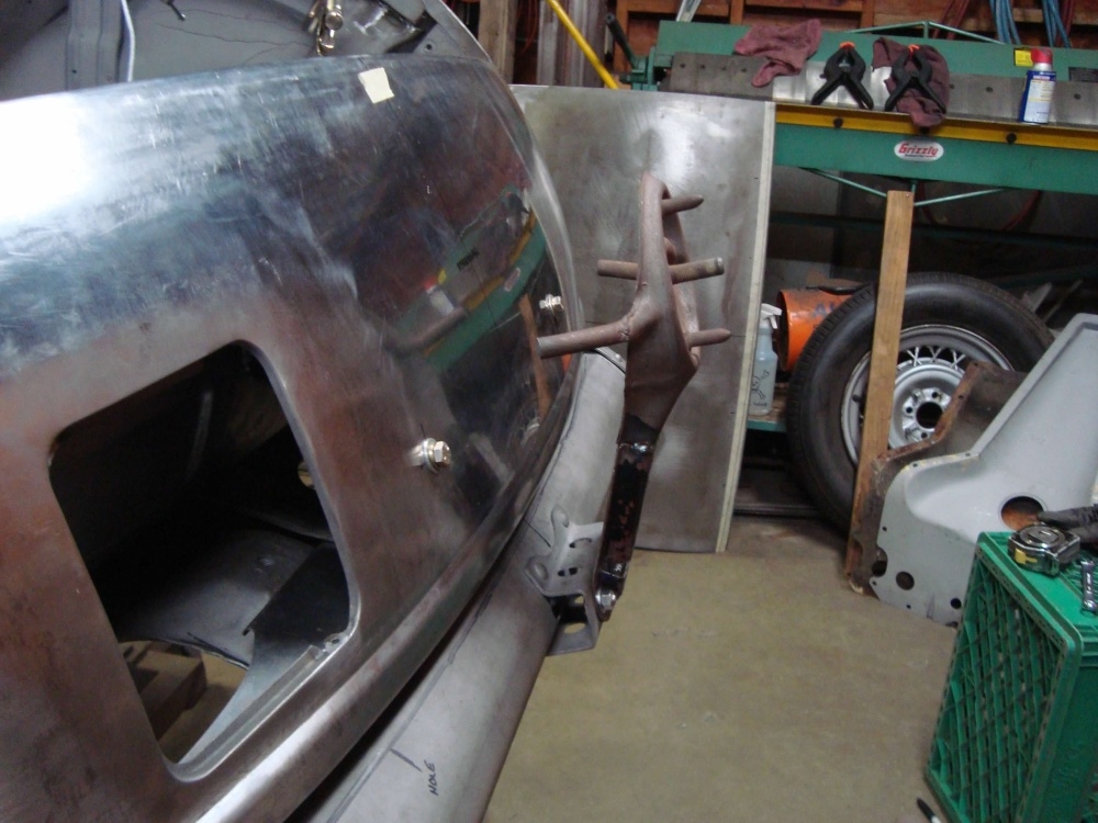
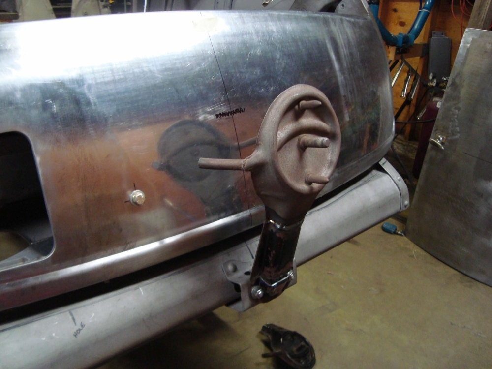
0 -
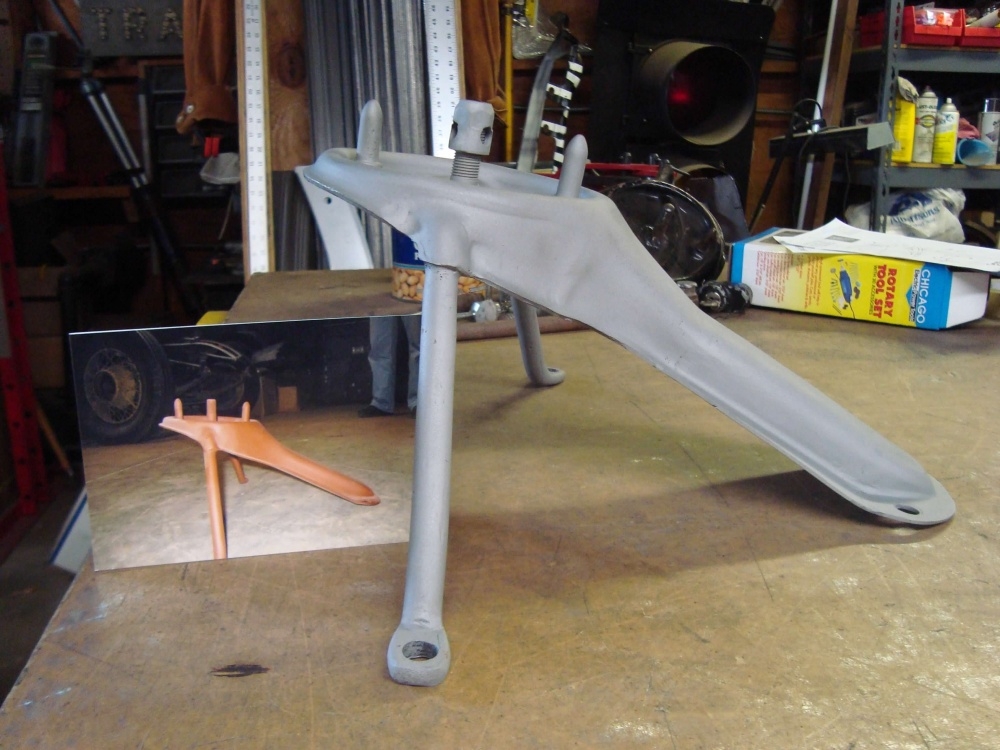
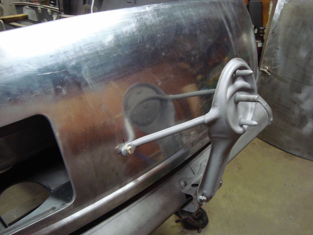
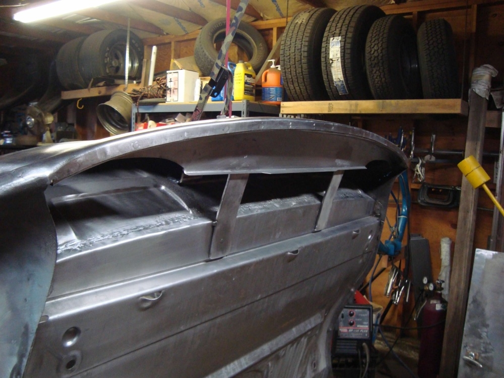
This is what I came up with. You can't just mount this bracket to the sheet metal rear panel. The sheet metal would never support the weight of the spare tire. On the back side of the sheet metal is a quarter inch thick bracket with captured nuts for the spare tire arms to bolt to. This bracket was fit to the back side of the sheet metal carefully so as to not distort the sheet metal when the spare tire bracket is bolted down. In the second picture I bolted the spare tire bracket down tight to make sure the sheet metal was not being distorted when tight. ...You can barely see the corner of the re-inforcement bracket in the last picture.
0 -
Then I was told the rims will be five lug, not the factory four lug. I would need to change the mounting bracket to accept the five lug wheels and also still use the factory wheel lock. The new five lug wheels have a larger center hole opening, so the original lock wouldn't work. ...I had to give this some thought. Here is what I came up with.
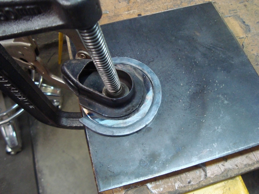
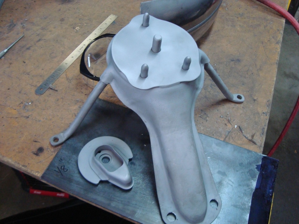
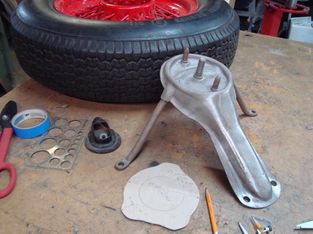
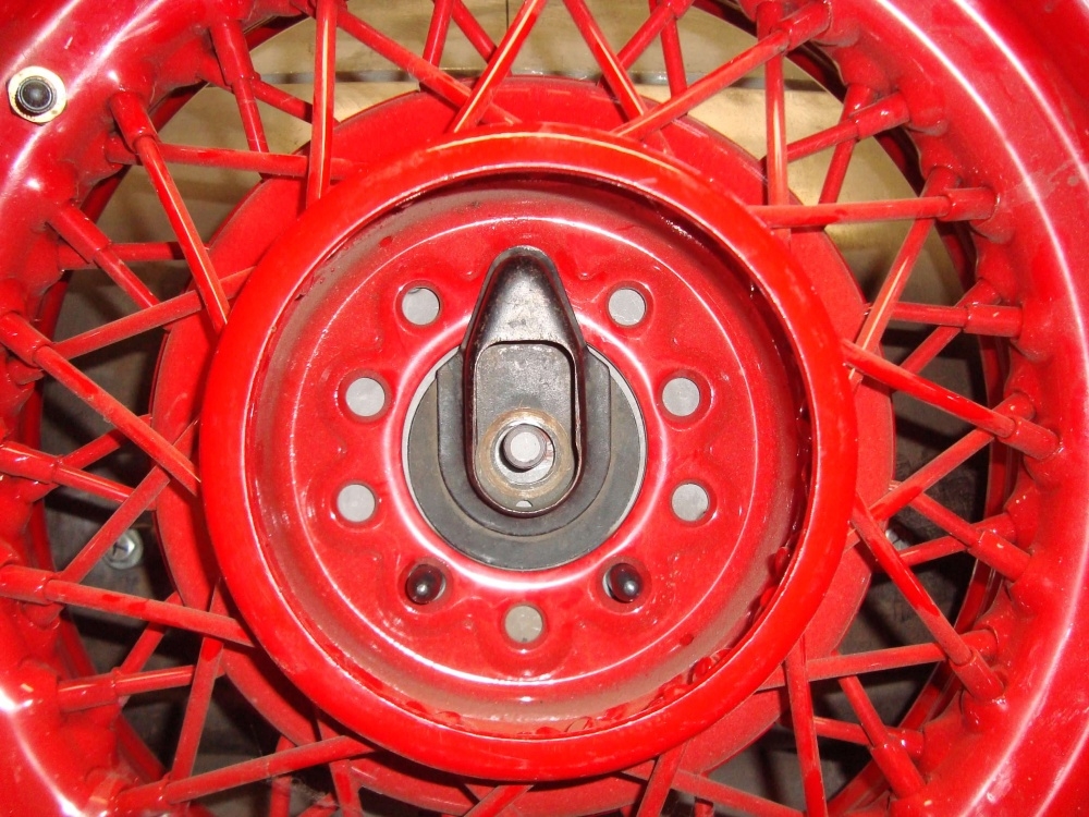
0 -
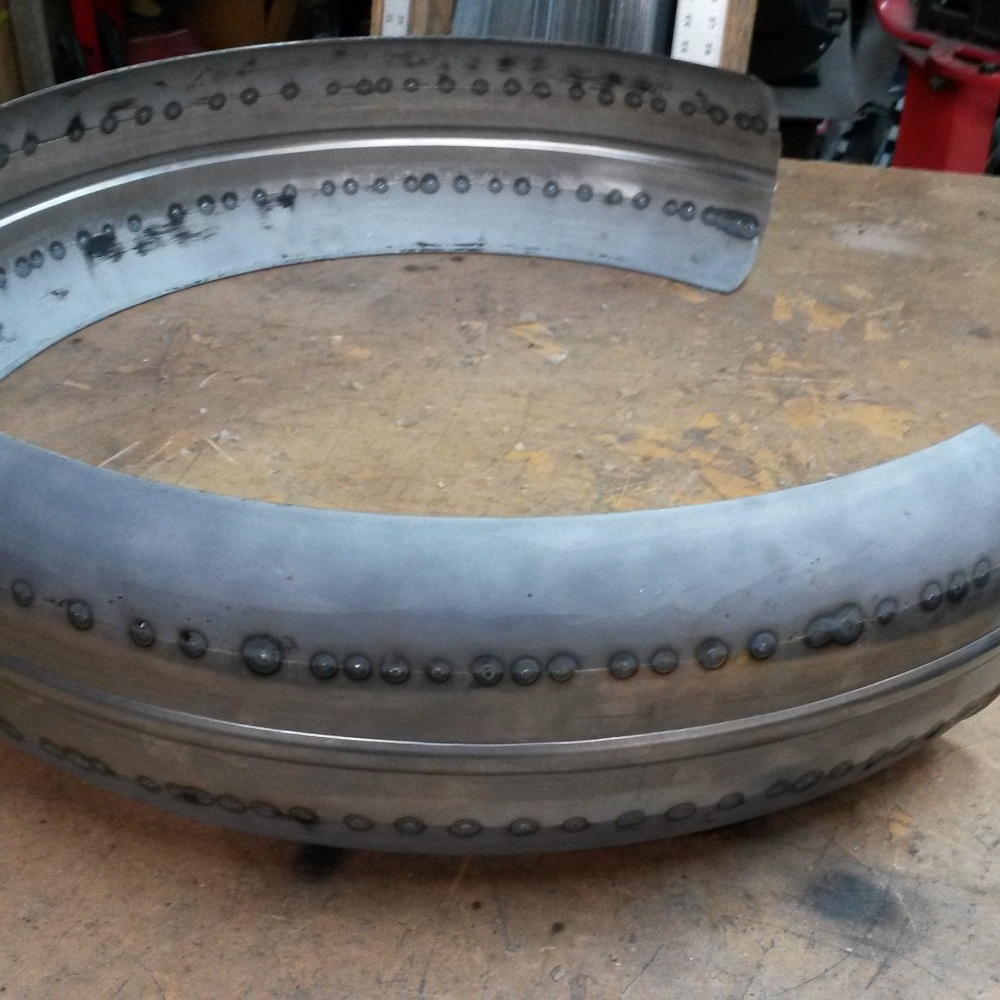
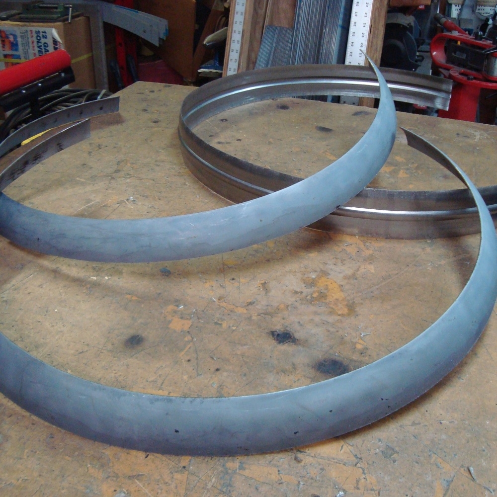
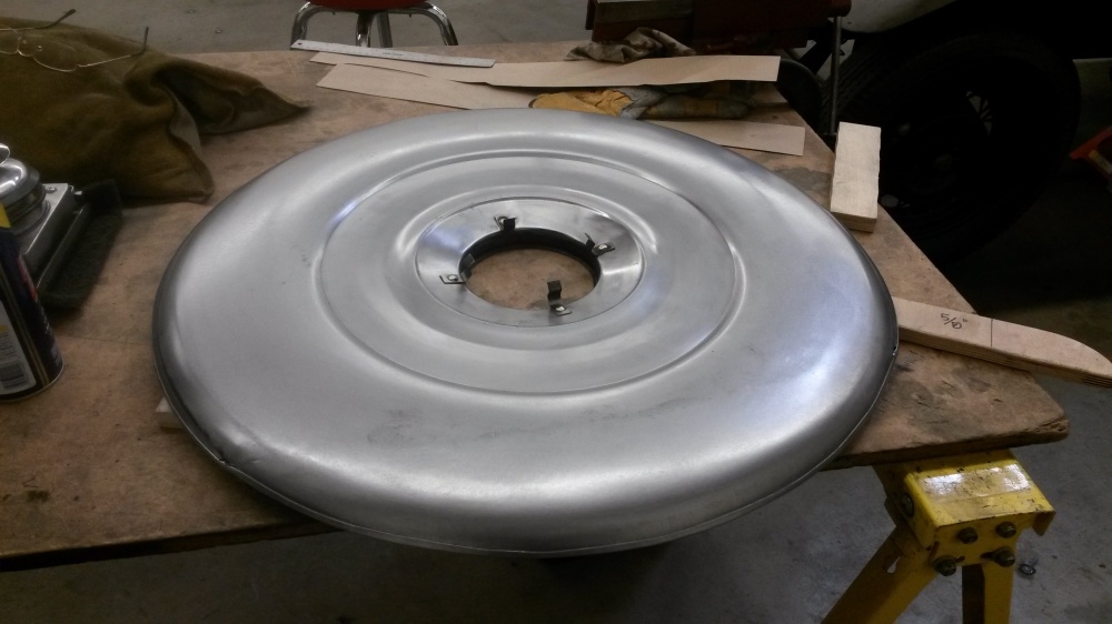
The new five lug wheels were also wider. Which meant the original spare tire cover wouldn't fit. I cut the original in half, made a new wider center section and welded the sides back on.
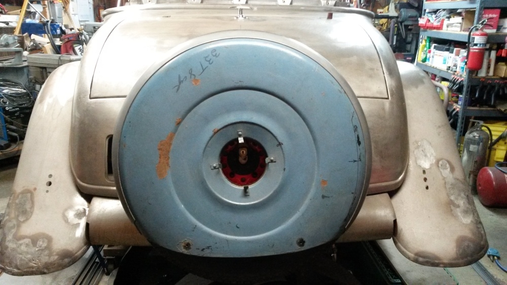
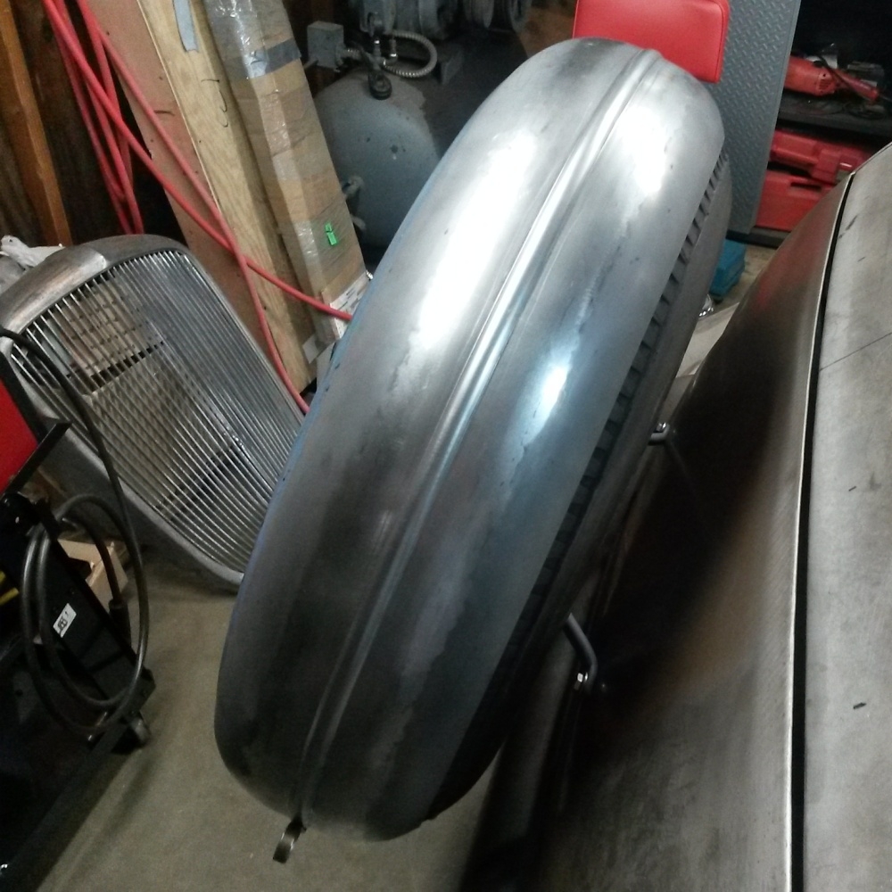
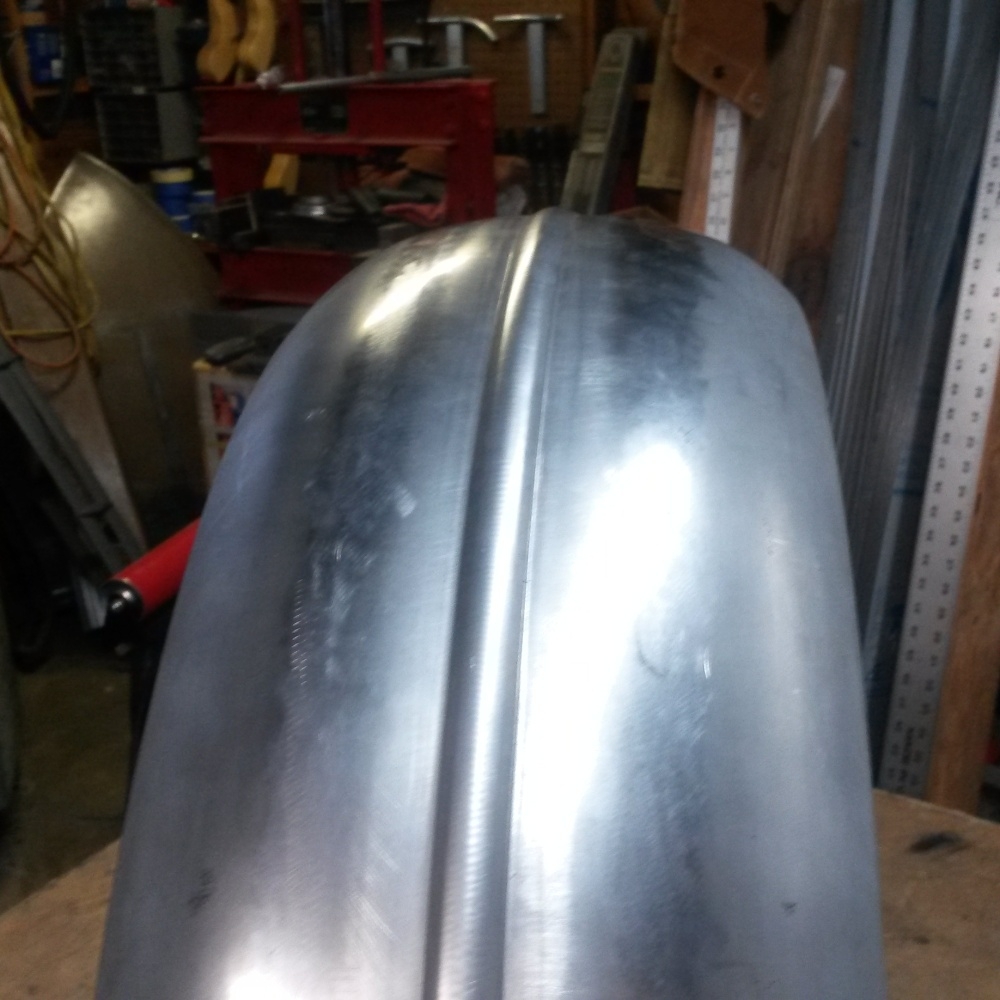
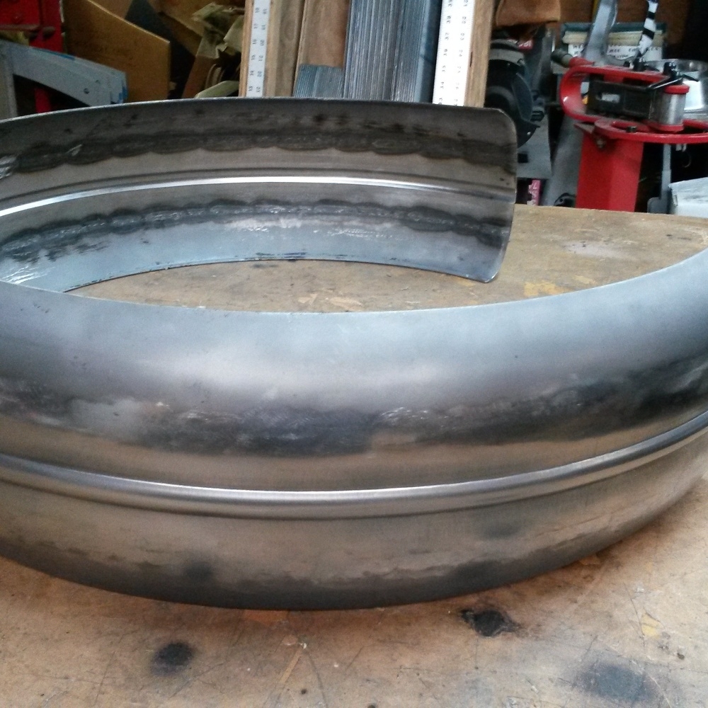
0 -
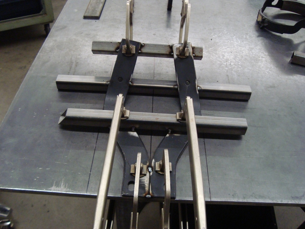
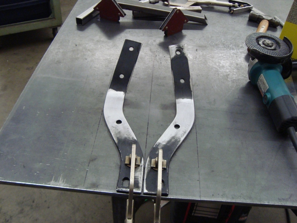
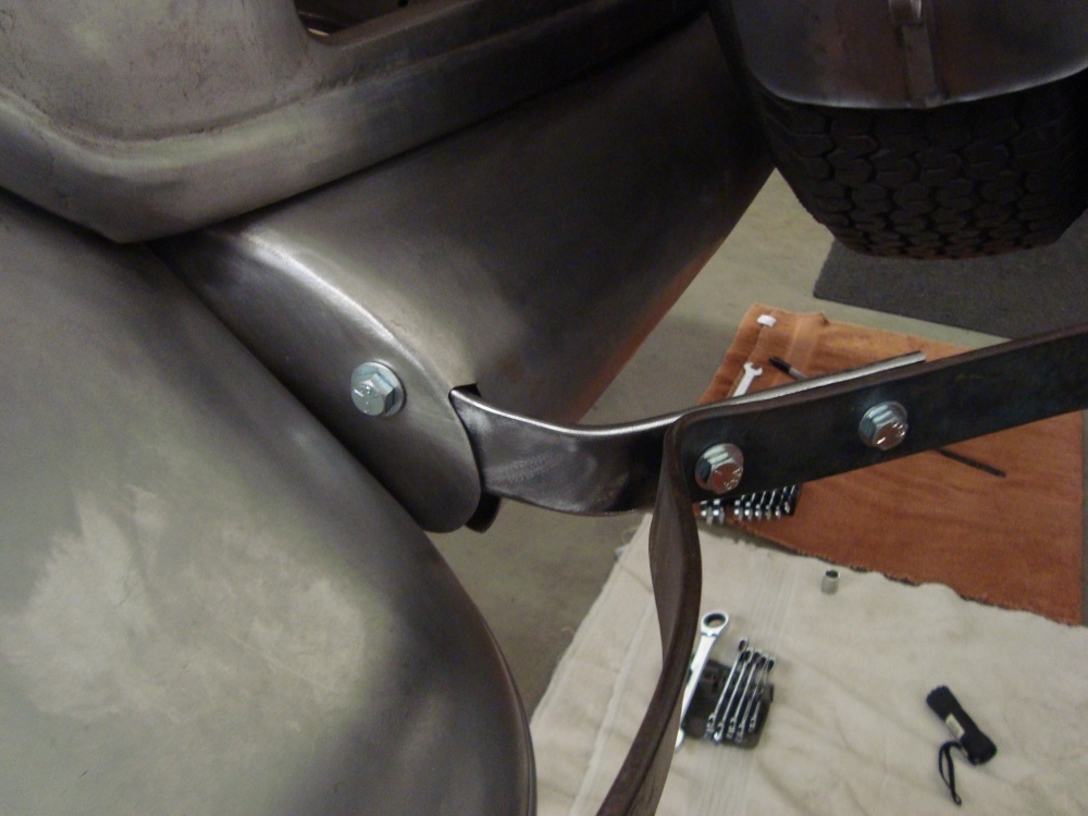
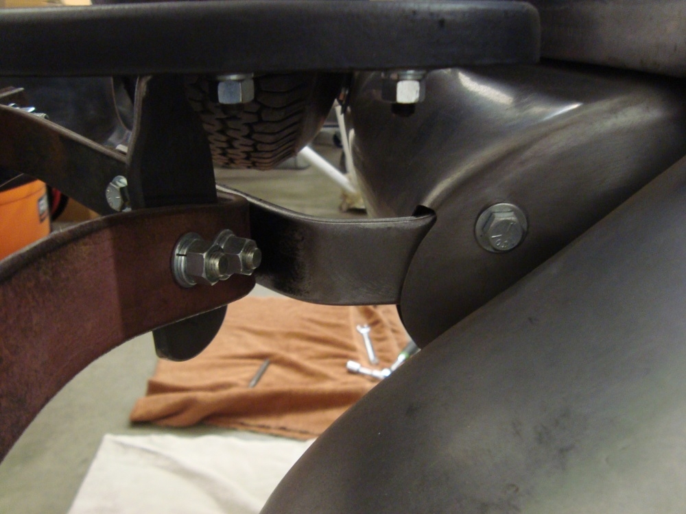
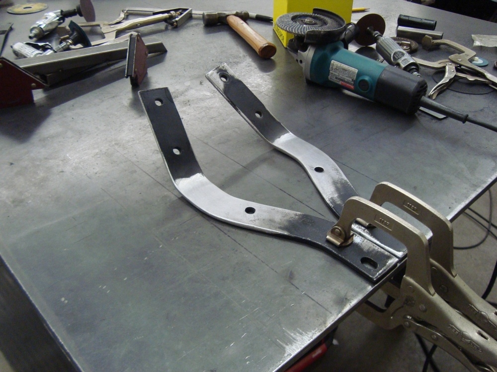
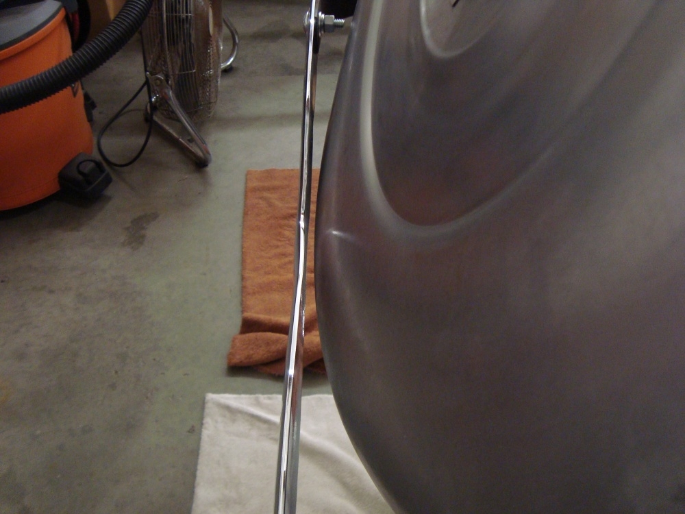
Doing all of this with the spare tire meant that the bumper would no longer clear the spare tire. So I extended the bumper brakets to clear the spare tire, but still look factory. Think I added an inch or an inch and a half? Can't remember. But it gave about a half inch clearance around the spare tire.
0 -
The spare tire cover we had was for a side mount, so the bottom was cut off to fit down in a side mount fender. Ivan wanted to wheel cover to be a full circle.
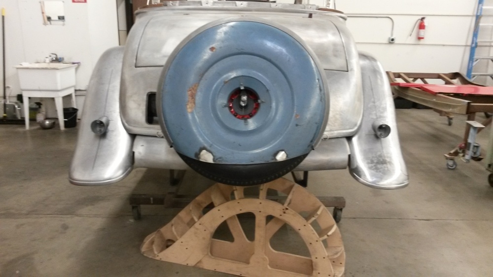
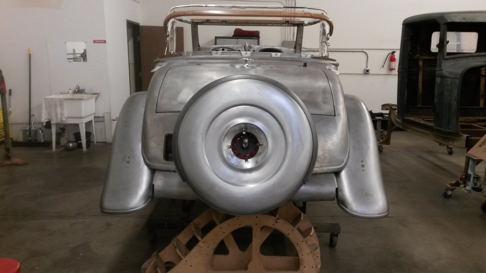
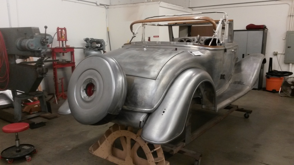
0 -
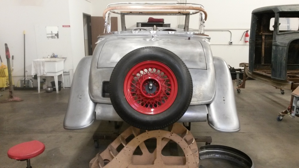
I kinda' like it with no cover at all. The red spoke wheel looks sporty to me.

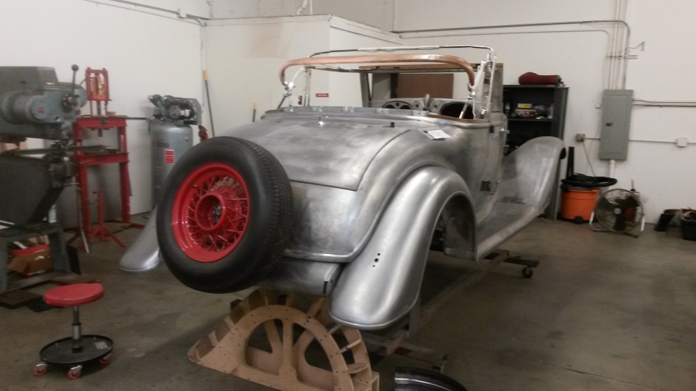
0 -
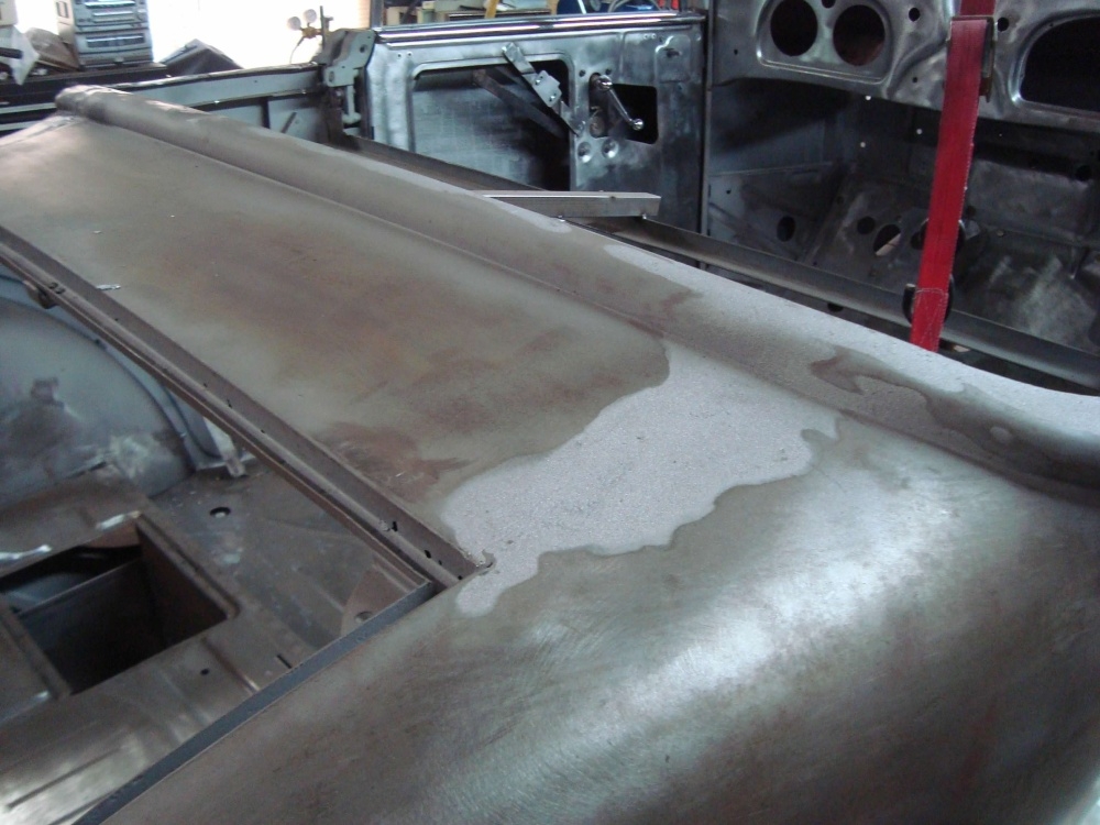
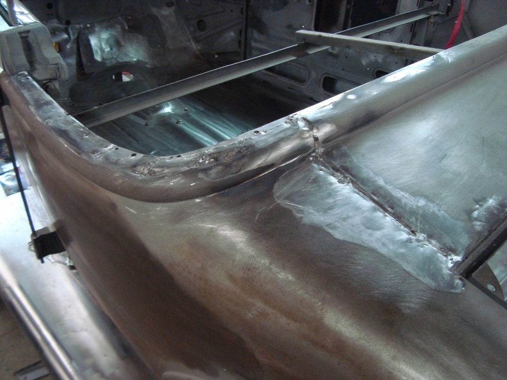
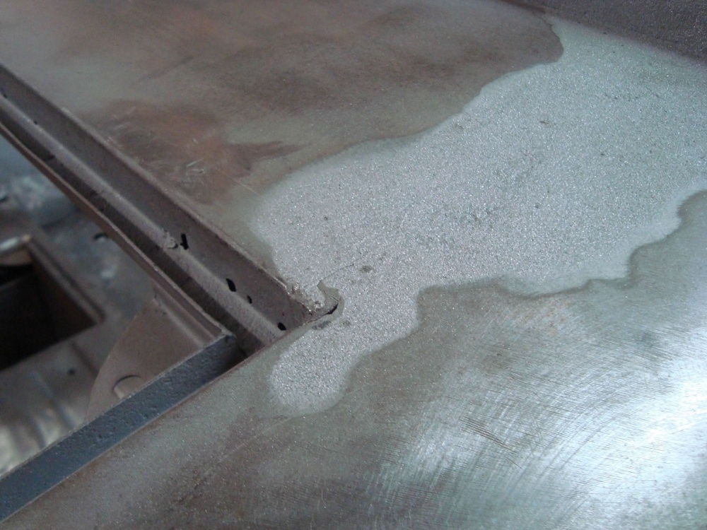
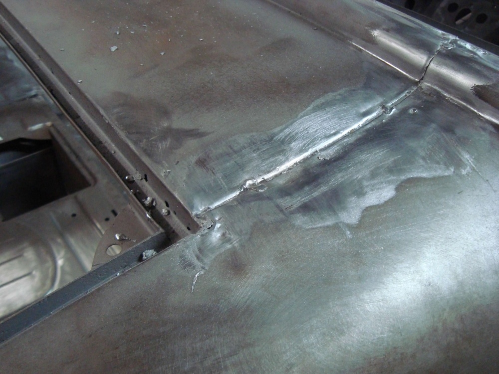
At some point in all of this I took a look at the cat walk and rumble seat gutters. Their were rust holes in and around the lead joints, and lead up around the back of the cab. Once the lead was removed I could see what needed to be done. Notice at the top of the cat walk, across the cab back the convertible top flange is missing. But I can see the outline of where it was cut off. All of the factory lead joints were "caved and paved". We can do better.

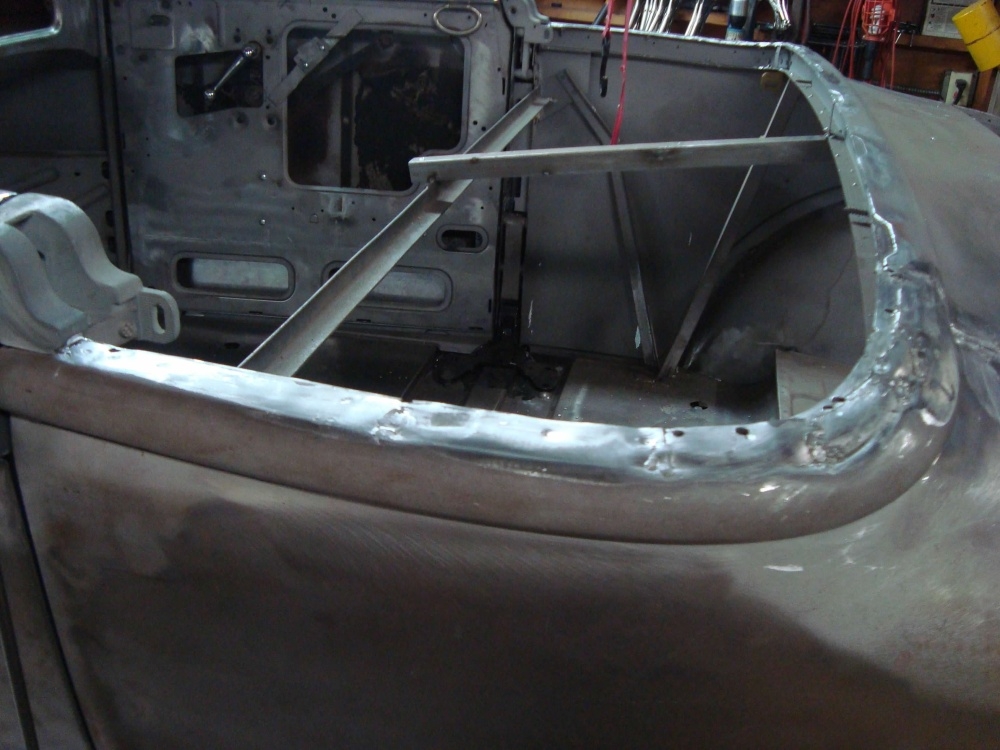
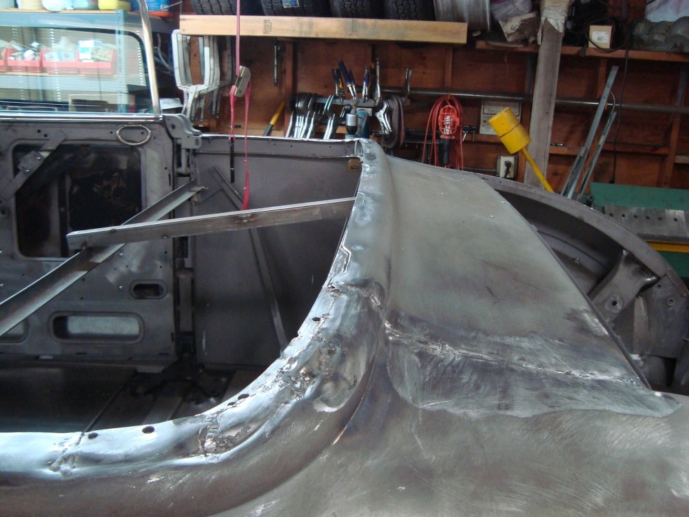
0 -
I decided to make the flange first. I had a picture of a car with the flange still on it and went from there. This flange is a little trickier than it looks. It's curved in two directions, over the top and around the back.
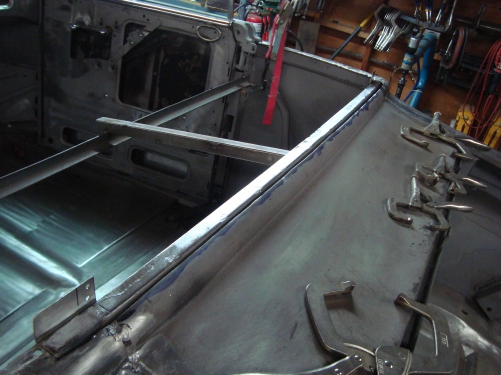
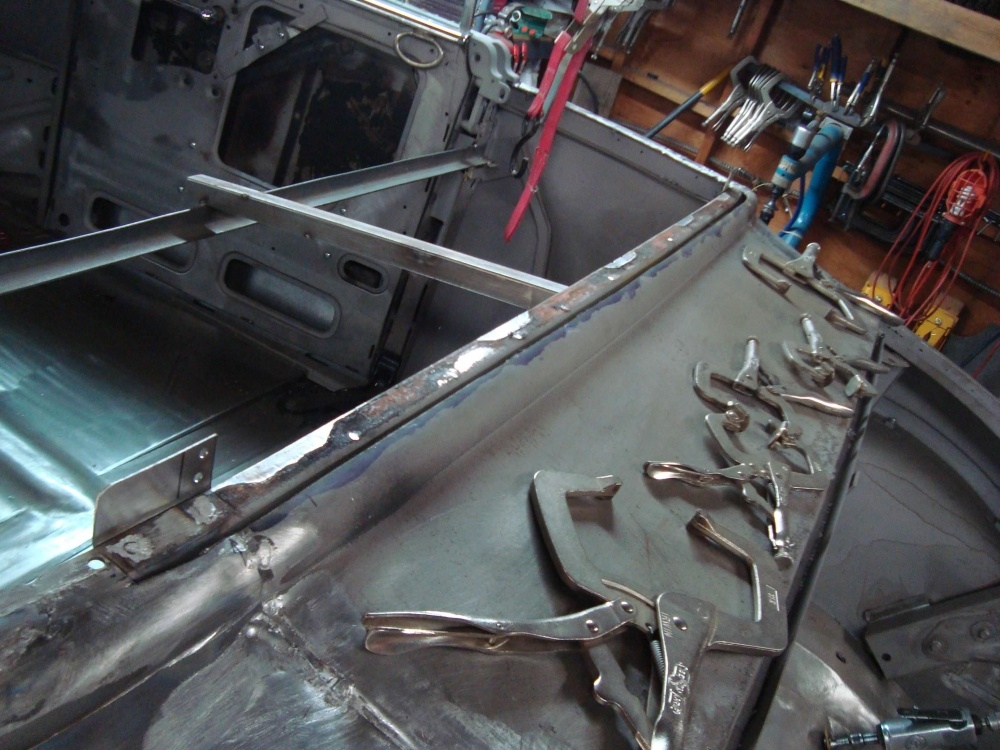
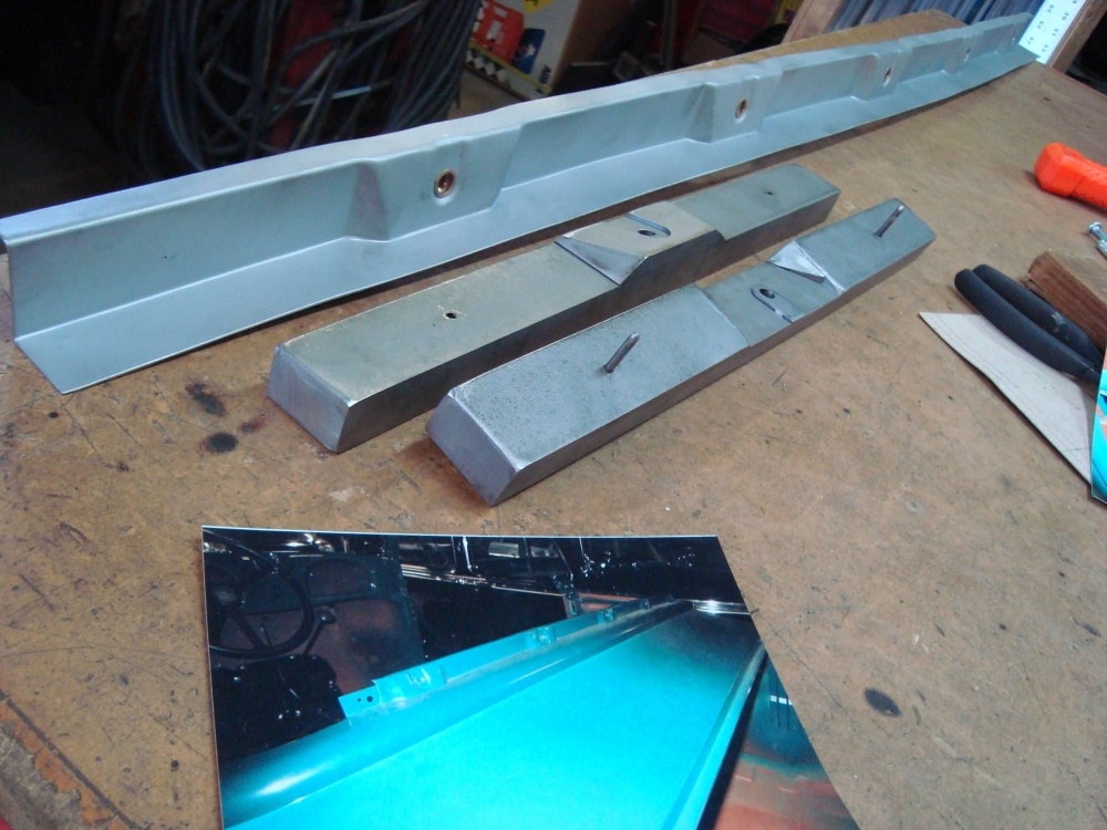
0 -
The new flange welded in.
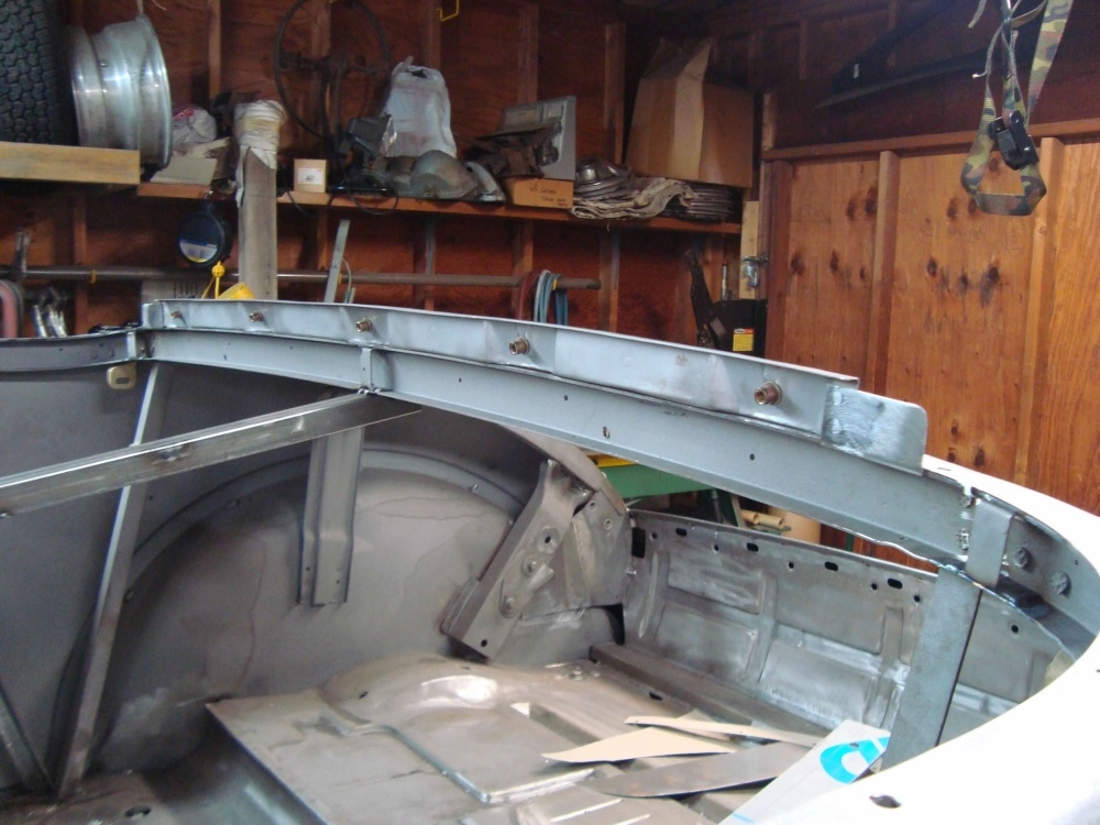
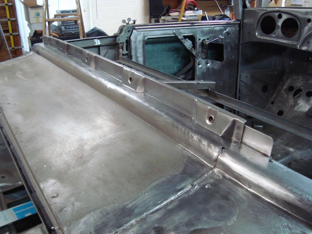
0 -
Time to look at the lead joints. Most of this is factory. ...Pretty bad. But we can clean it up.
 The inner structure stuff was cleaned, repaired if needed, then primed before the area was welded closed.
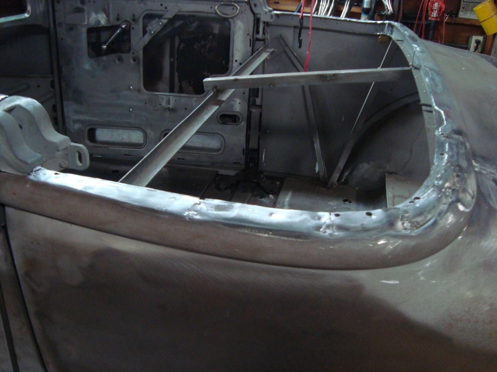
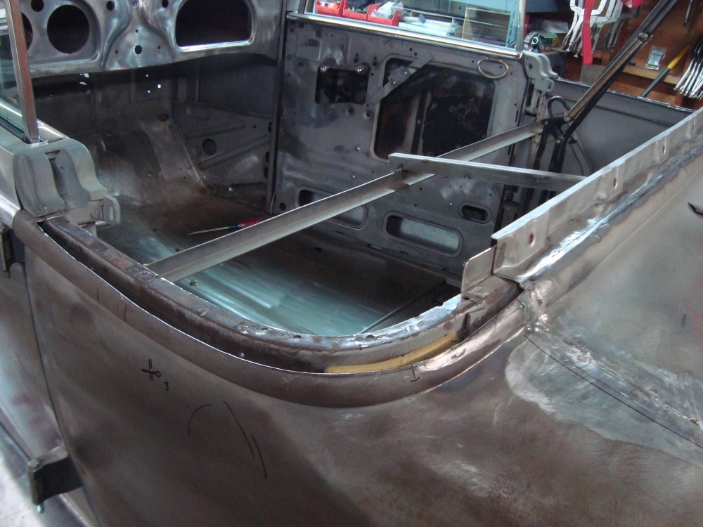
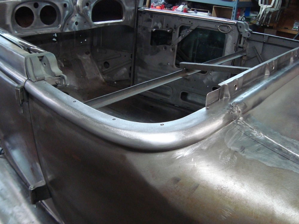
0 -
Both sides.
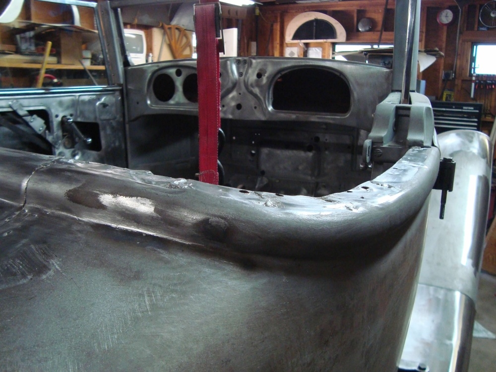
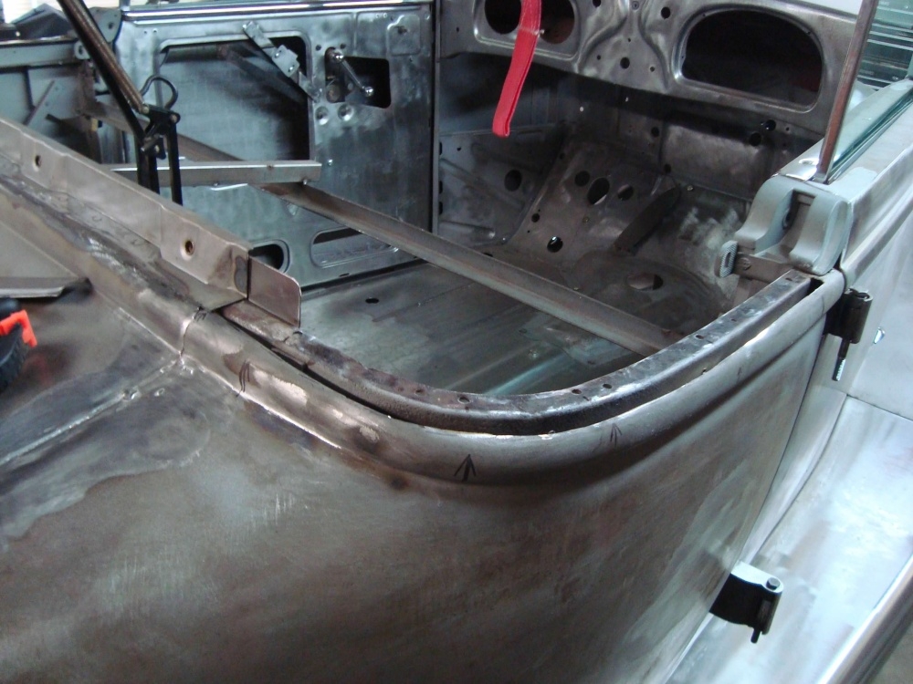
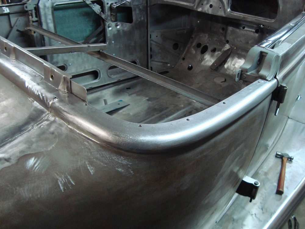
0 -
Then the lead seams across the cat walk. Notice I didn't finish the cat walk where it meets the rumble seat gutter. That's because I have to remake the gutter too.
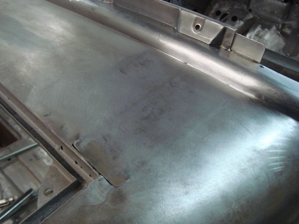
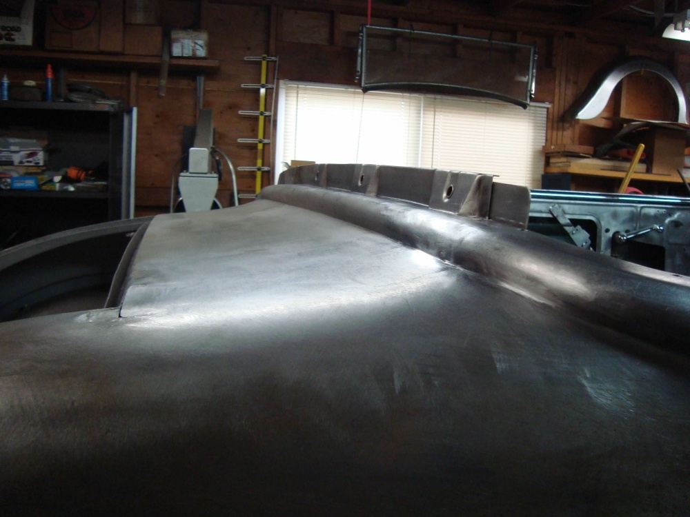
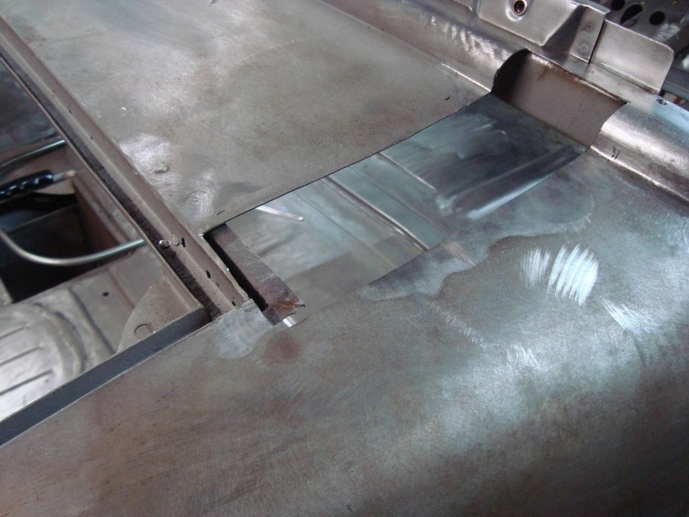
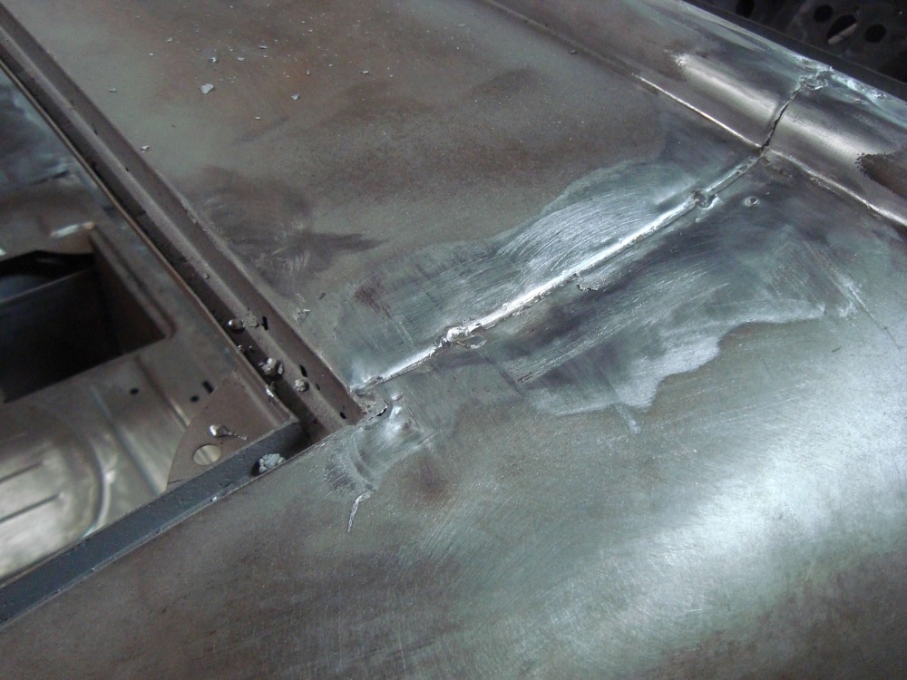
0 -
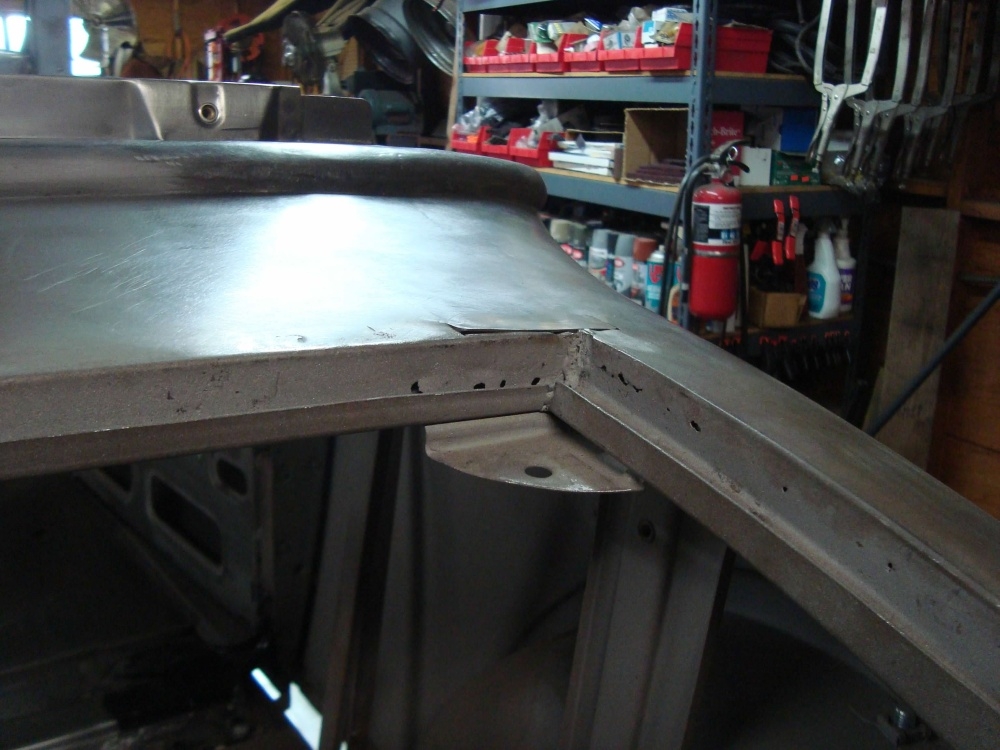
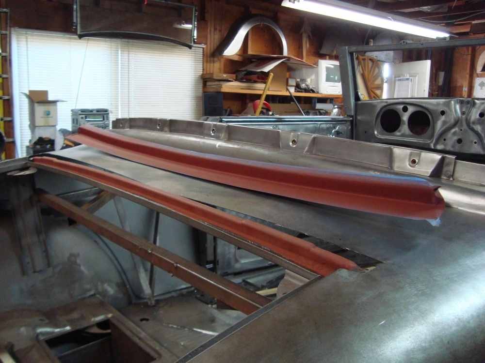
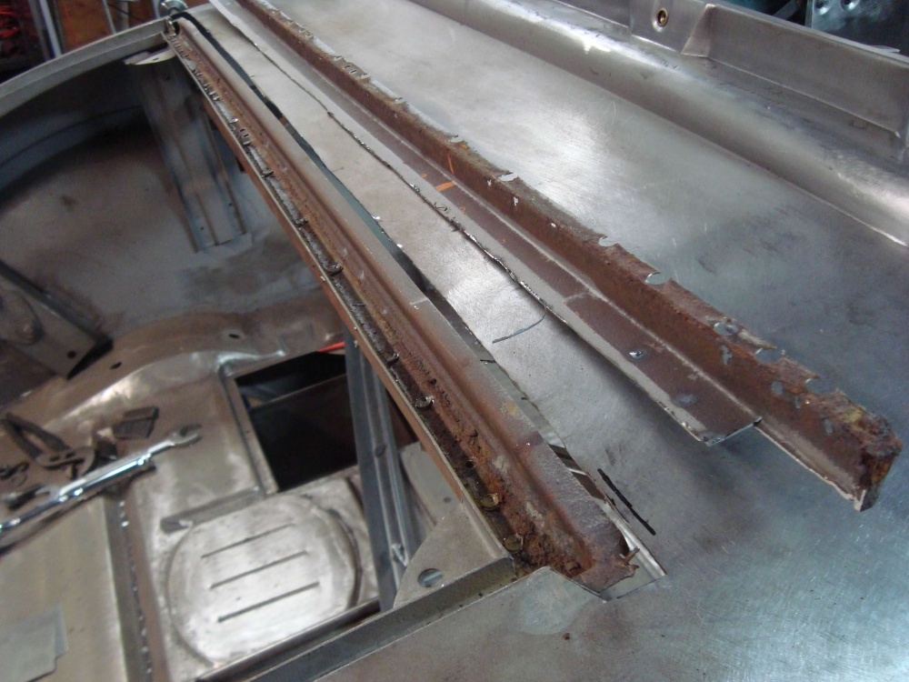
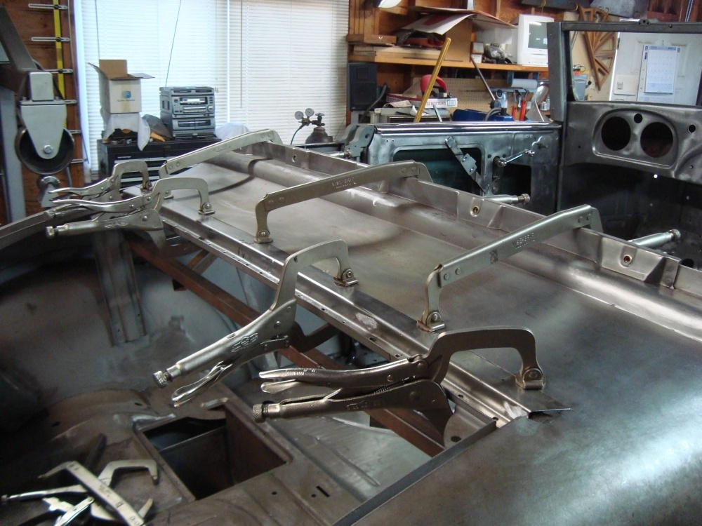
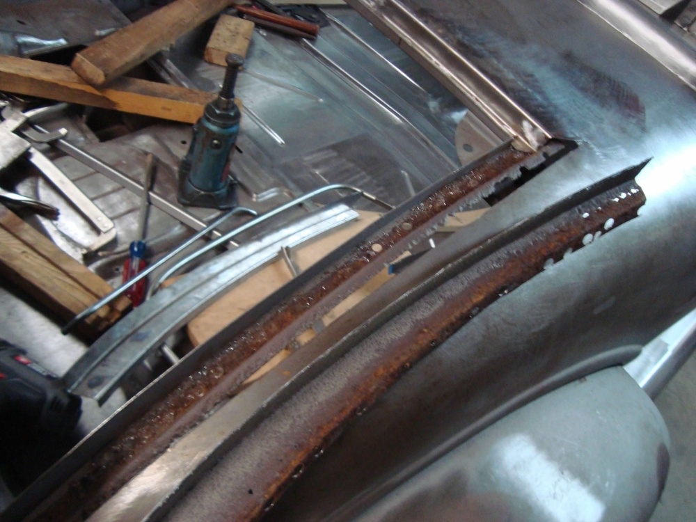
The rumble seat gutter. In the second picture you can see the rust coming through from the back side of the gutter, showing up as pin holes.
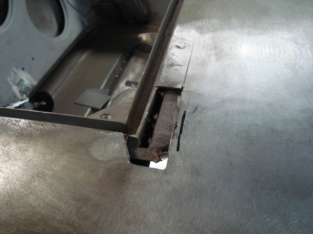
0 -
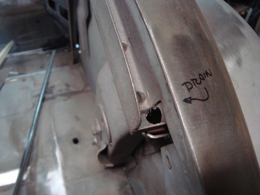
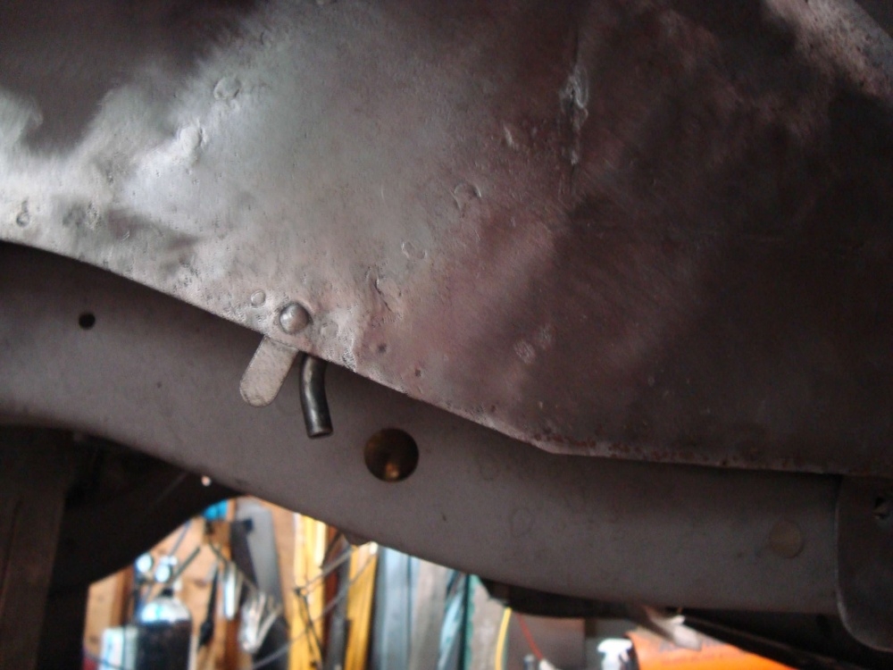
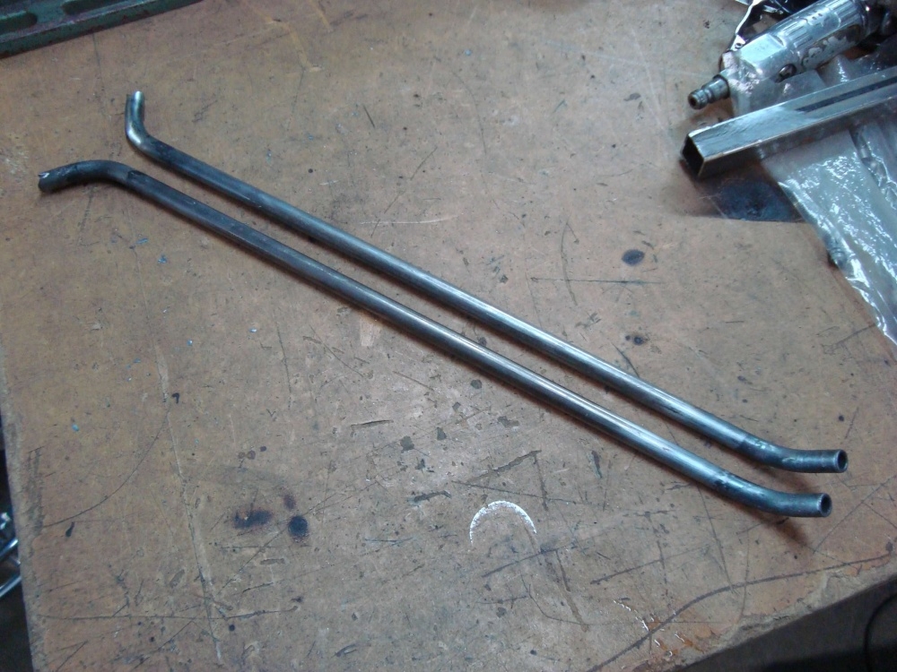
The rust continued on. Up one side and down the other. We also decided to install a drain tube in the bottom of the rumble seat gutter. This tube exits below the floor and behind the rear tire.
0
Categories
- 37K All Categories
- 113 Hudson 1916 - 1929
- 21 Upcoming Events
- 93 Essex Super 6
- 28.6K HUDSON
- 576 "How To" - Skills, mechanical and other wise
- 995 Street Rods
- 151 American Motors
- 180 The Flathead Forum
- 49 Manuals, etc,.
- 78 Hudson 8
- 44 FORUM - Instructions and Tips on using the forum
- 2.8K CLASSIFIEDS
- 608 Vehicles
- 2.2K Parts & Pieces
- 77 Literature & Memorabilia
- Hudson 1916 - 1929 Yahoo Groups Archived Photos
