46 Super Regulator Wiring

Comments
-
A terminal goes to the Armature terminal on the generator. F terminal goes to the Field terminal on the generator. T terminal goes to the panel gauge indicating 'Oil'. B terminal goes to the battery side of the starter solenoid on the starter as well as a wire going to the B terminal on the fuse block.
0 -
His regulator is not marked.
0 -
eddiehudson, the terminal tabs on the VRR 4001 A voltage regulator he uses has 4 terminals. They are marked on the VR base as to which terminal they are .Either A,B,F or T .
0 -
Sorry to disagree - the "T" terminal connects to the Gen. indicator light on the dash, not the oil light.
0 -
I appreciate the input so dar but I do have a wiring diagram. What I don't have is which terminal is which on the regulator. Mine is completely unmarked.
0 -
Yep you're right Geoff. Eyes are getting old. LOL
0 -
Look on the VR base ( the silver part). Scratch some of the crud off the sides of the base next to the terminal tabs. There are letters indicating which terminals are which.
0 -
I found the hudson document on how to test the regulator and it has a diagram of the internals of the regulator, so I took off the cover and mapped out the pins, and low and behold, some find stamp marks are by the pins below where I couldn't see them with the cover on. Thanks to all who responded, now I can test it out!
/dan
0 -
Curious why the B terminal would go all the way down to the starter when the battery is right next to the battery?
0 -
It is not usual to take any circuits from the battery direct, apart from the main lead from the battery itself to the starter solenoid (or switch) terminal. I understand that this is to protect against acid corrosion from creeping along the wire, but others may come up with a better reason.
0 -
Hello, I am reading about your efforts with your 1946 charging system.
Do you know that it is a 3 brush generator? The regulator moderates ONLY VOLTAGE, not amperage.
The third brush slides/pivots closer and farther from the other brush and the position of the third brush SETS THE AMPREAGE. Way back when, a service man would slide the brush to make more current (amps) in the (dark) winter when you used your lights and back it off in the summer so that you would not boil off the water in your battery.
Three brush charging systems were the industry standard during the 20s and 30s. (during these years the 3rd brush regulated amperage and the BATTERY itself regulated the voltage. If you disconnected your battery the voltage would increase continuously (20+ volts?) and pop any light bulbs that were on. Using a regulator for voltage stopped this problem. An improvement Hudson added by the early 40s
By about 1940 most of the industry automakers went to a 2 brush generator with a regulator that moderated BOTH voltage and amperage. Ford changed in 1940. Hudson kept the 3 brush voltage regulated design until midway through 1950(?)
This is why your 1947 regulator has only 2 relays (cutout and voltage) and the typical generator regulator (2 brush system) has 3 relays (cutout, voltage, current)
Once your system is functional you will need to slide the third brush back and forth (with an amp gauge in the circuit) while the car is running to set the correct operating amperage.
Search 3 brush generator on the web, there are some good articles out there.
0 -
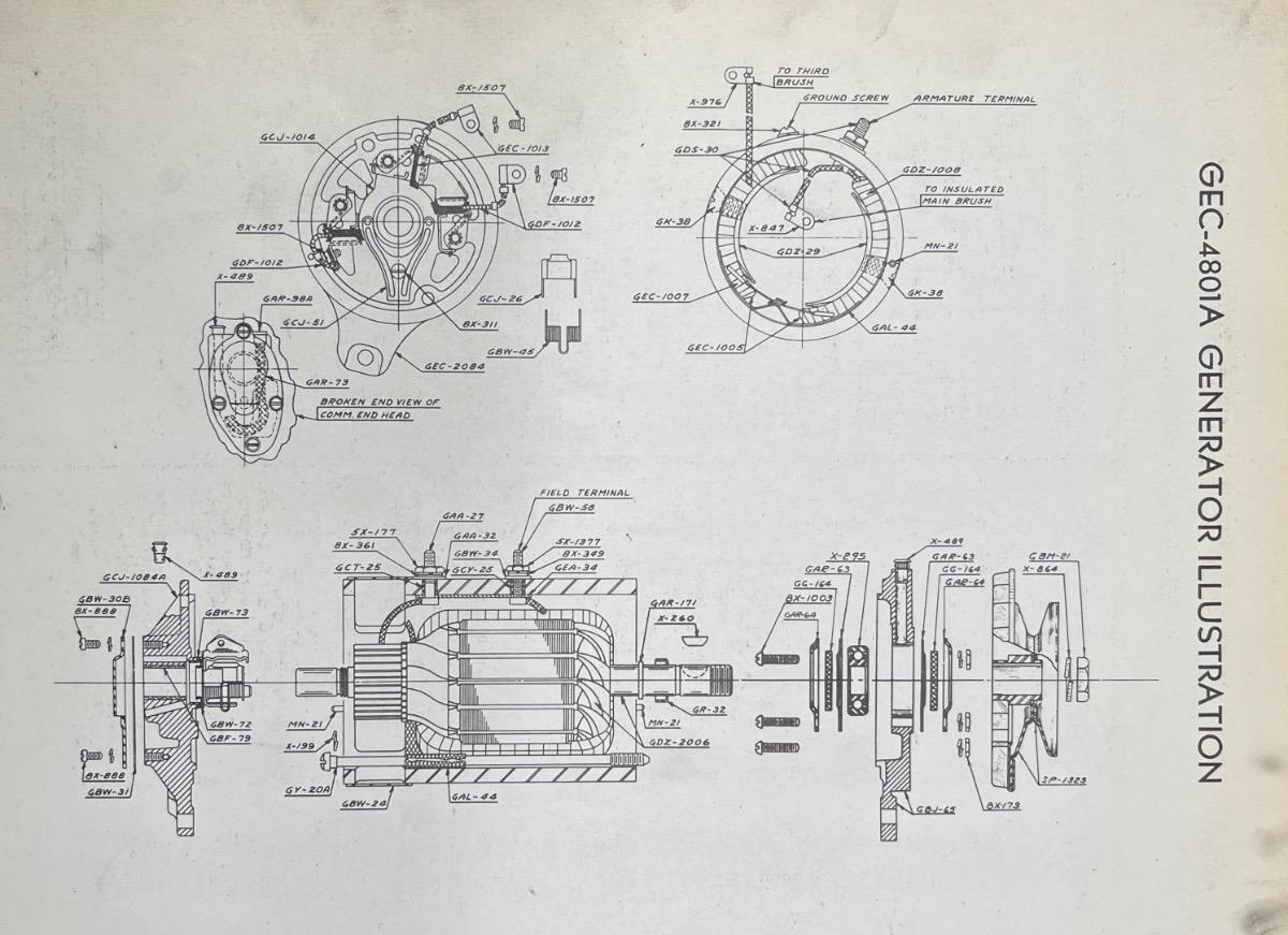
This was all items that I didn't know, but do in detail now! I was able to find a generator document from Autolite from 1939 on the GEC4801A. I have attached the page of interest that shows how the field and armature are wired with the 3 brushes. It is actually a beautiful drawing, made by a great draftsman. It was from this that I discovered that when mine was rebuilt, the armature was connected to the third brush, not the field coil.
enjoy!
/dan
0

Categories
- 37.1K All Categories
- 120 Hudson 1916 - 1929
- 21 Upcoming Events
- 100 Essex Super 6
- 28.7K HUDSON
- 595 "How To" - Skills, mechanical and other wise
- 995 Street Rods
- 151 American Motors
- 185 The Flathead Forum
- 49 Manuals, etc,.
- 79 Hudson 8
- 45 FORUM - Instructions and Tips on using the forum
- 2.9K CLASSIFIEDS
- 612 Vehicles
- 2.2K Parts & Pieces
- 78 Literature & Memorabilia
- Hudson 1916 - 1929 Yahoo Groups Archived Photos