new front stub frame in my '49 brougham
lsfirth
Expert Adviser
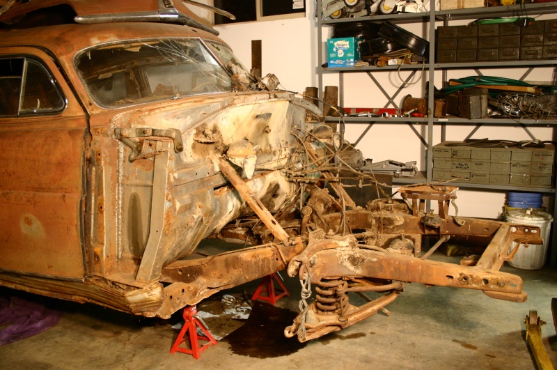
Okay, finally getting a chance to give an update on my sub frame progress. A couple months ago I ordered a Fatman Fab stub frame for the '49 Hudson. It showed up about 5 weeks later and I went and picked it up from Conway Trucking down in south Renton. To my surprise it was only ~$120 to have it shipped from North Carolina. Saved about $100 bucks by picking it up with my truck in their yard. Anyway, brought it home and uloaded it from the back of my truck. By this time I had the entire front clip off the Hudson. The following pictures somewhat provide a step by step process of cutting off the old stub frame and positioning the new one.
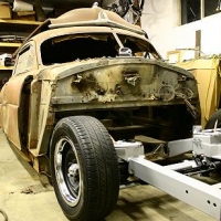
Here's the clip removed:
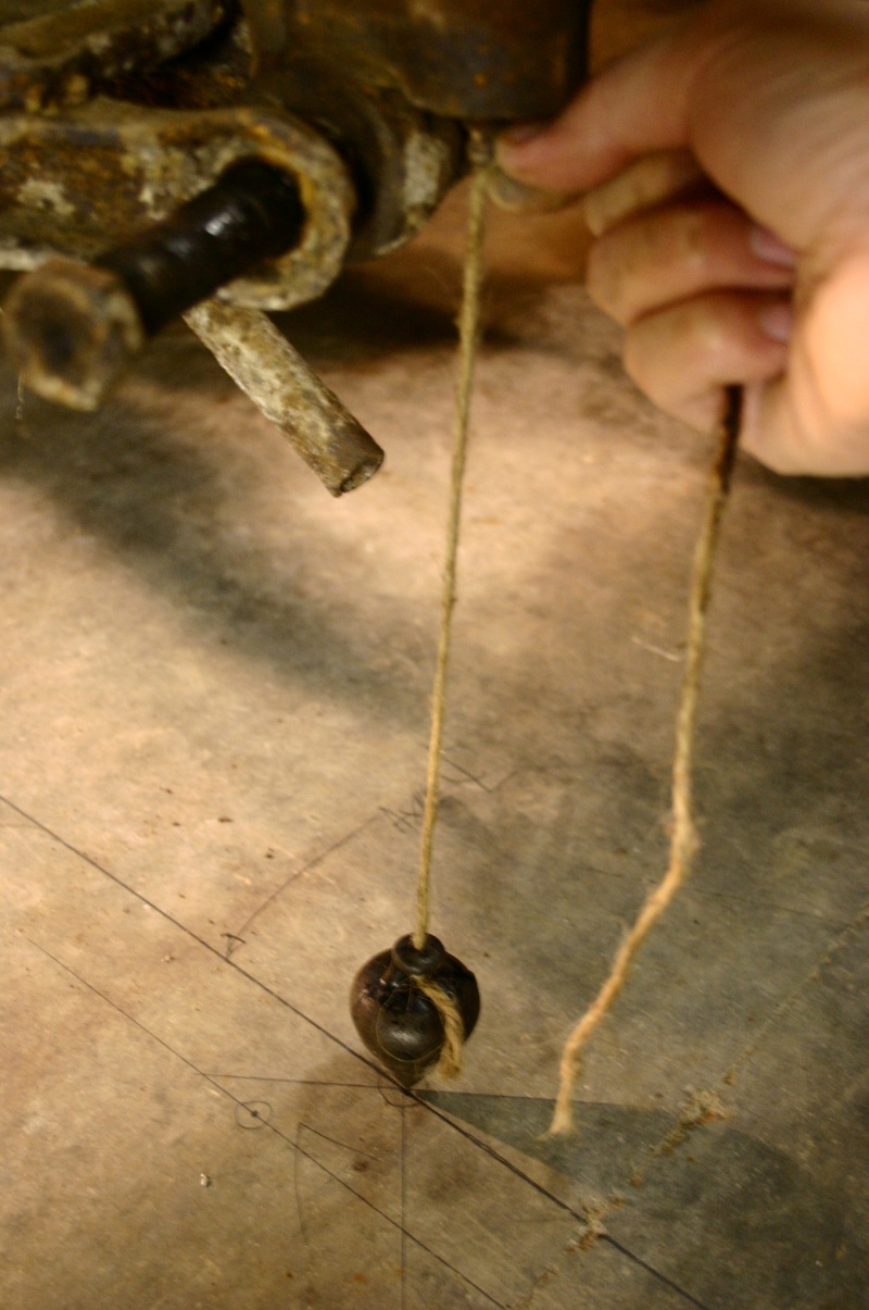
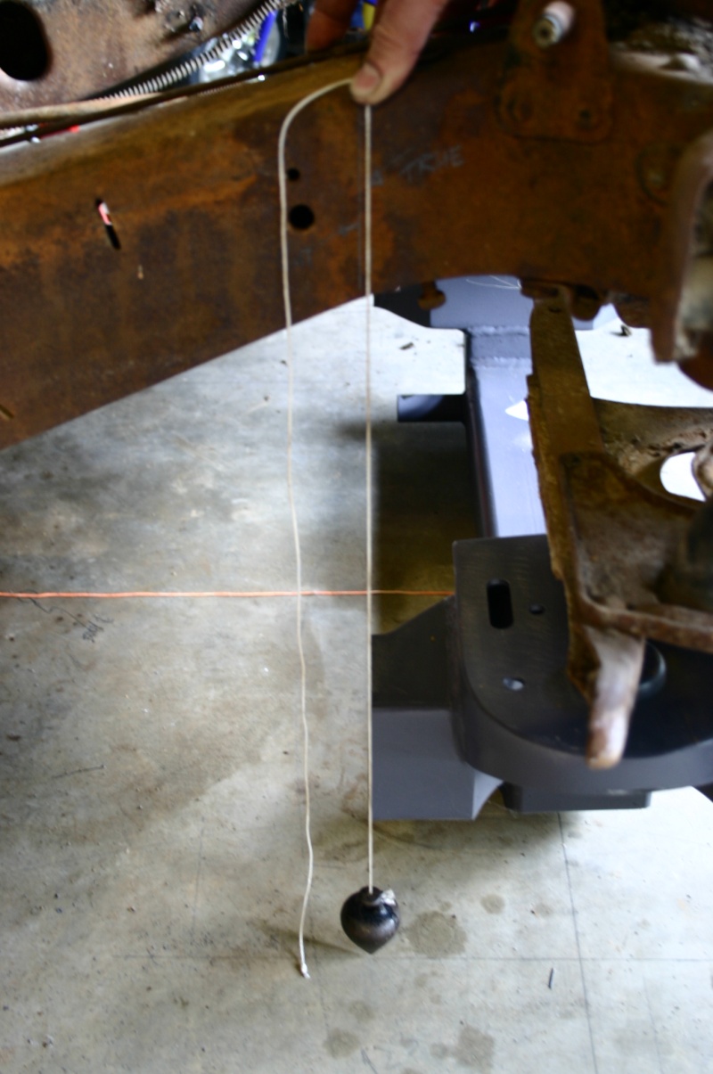
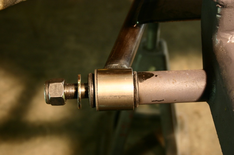
The first thing to do is try to precisely locate the front axle centerline and mark it on the floor - need a plumb bob for this:
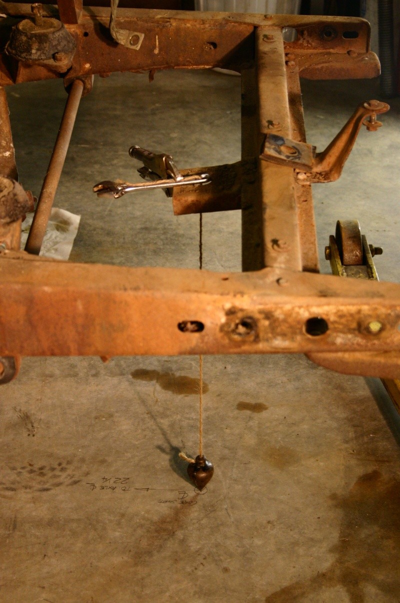
Then you need to precisely locate the radiator core support since this essentially locates the entire front clip (fenders, grill, hood, etc). Mark this point on the floor and measure how high it is from the floor. The same needs to be done for the bumper bolt holes in the frame.
Here's where I departed from the instructions somewhat. They wanted me to cut the frame at a measured distance from some rivets on the old frame under the firewall. I figured that I could better align the new stub by locating it directly under the old sub-frame then use the plumb bob to locate the cut location. I cut an extra 1/8th of an inch off to leave a gap to fill in with weld when the new one goes on.
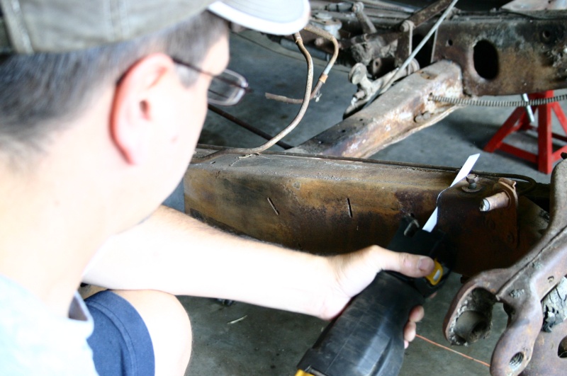
Once I was happy with the alignment, marks on the floor, and cutting lines on the old frame, it was time to bust out the sawsall. At one point I asked my friend if I should take the old brake lines off and get them out of the way.....he promply replied "those fall into the 'all' category of the sawsALL". We both laughed and I started sawing.
I'll post more pics as I have time!
Lee
Here's the clip removed:
The first thing to do is try to precisely locate the front axle centerline and mark it on the floor - need a plumb bob for this:
Then you need to precisely locate the radiator core support since this essentially locates the entire front clip (fenders, grill, hood, etc). Mark this point on the floor and measure how high it is from the floor. The same needs to be done for the bumper bolt holes in the frame.
Here's where I departed from the instructions somewhat. They wanted me to cut the frame at a measured distance from some rivets on the old frame under the firewall. I figured that I could better align the new stub by locating it directly under the old sub-frame then use the plumb bob to locate the cut location. I cut an extra 1/8th of an inch off to leave a gap to fill in with weld when the new one goes on.
Once I was happy with the alignment, marks on the floor, and cutting lines on the old frame, it was time to bust out the sawsall. At one point I asked my friend if I should take the old brake lines off and get them out of the way.....he promply replied "those fall into the 'all' category of the sawsALL". We both laughed and I started sawing.
I'll post more pics as I have time!
Lee
0
Comments
-
Hope you don't make the same mistake my uncle and I made while installing a Fatmans frame stub onto his 41 Pontiac convertible. We had the car sitting on jack stands, had made all the careful measurements and marks on the floor using the plumb bob. Since this was our first time making this modification we really went slow and measured, marked then remeasured. Then when sawing thru the last bit of the old frame, BAM!
We had placed the rear jack stands in front of the rear axle. Thus, when the weight of the front frame was gone, the whole car tilted backwards onto the floor causing us to lose all our careful measurements and marks on the floor.
We sat the car back up level (with rear jackstands now behind the rear axle), took the old frame section and clamped it back into place and remarked all the measurements on the floor (after erasing all the old ones).
It was a learning experience but the job was completed and the car is driving straight and all body panels aligned perfectly! Looking forward to seeing that stepdown when you're done!0 -
Yeah I kept everything level and stable on 4 jackstands under the frame at each corner of the car and kept it there until I had everything welded in place. I'll try to put some more pics up tonight. I'm really happy with it so far other than having to make a few mods to the Fatman stub in order to put JW Rod Garage components on. I thought MII would be MII and everthing would interchange.....wasn't quite so easy!0
-
"isfirth" I am considering a similar switch and live in NC so a fatman is a choice locally,but did you consider a Firebird/Camero of say mid 80's as an option ? These old GM subs actually unbolt from the box of their parent car and are usually avaliable for $100. We bought one for the local automotive dept at the Comm.College and had it blasted and repainted. New components all added up to around $550 more and the disc brakes etc seem to fill a need. We plan to put this on a 54 when another grand check comes forth.0
-
Looks like quite the undertaking!!
Just one question was the origional clip damaged is some way or you just wanted to replace it with some modern metal?
Just wondering looks like a good start..
Dusty
P.S. I have a Hornet with a cracked up front end and was going to replace it with another from a donor car but I'll be looking forward to watching this progress. Might change my mind. The brakes and power steering would be nice..0 -
coverton wrote:"isfirth" I am considering a similar switch and live in NC so a fatman is a choice locally,but did you consider a Firebird/Camero of say mid 80's as an option ? These old GM subs actually unbolt from the box of their parent car and are usually avaliable for $100. We bought one for the local automotive dept at the Comm.College and had it blasted and repainted. New components all added up to around $550 more and the disc brakes etc seem to fill a need. We plan to put this on a 54 when another grand check comes forth.
Well, I thought about trying to just keep the original suspension, but the passenger side spindle was missing and it had been sitting for a long long time, so all the rubber stuff was deteriorated and the rest of it was really crusty. After reading through the "frame stubs for fatties parts 1 and 2", the fatman stub seemed to be a pretty clean and already thought out approach. So I never really considered a front clip from another car. Definitely, the disk breaks and rack and pinion steering will be nice. The only drawback is the price......~$1000 for only the stub....and about $1500 for all the MII components.....OUCH.....wallet is still hurting!!
Lee0 -
esfoder wrote:Looks like quite the undertaking!!
Just one question was the origional clip damaged is some way or you just wanted to replace it with some modern metal?
Just wondering looks like a good start..
Dusty
P.S. I have a Hornet with a cracked up front end and was going to replace it with another from a donor car but I'll be looking forward to watching this progress. Might change my mind. The brakes and power steering would be nice..
Yeah....quite an undertaking is right. I don't feel like I'm over my head, but it's obvious that this will be a long term project. The clip wasn't damaged really, but there was some parts missing. I considered re-buildig the original clip, but I really want the car low....and I couldn't find any drop spindles and wasn't sure how I would "bag" the original front end. Also, the new breaks and steering should be nice.
Lee0 -
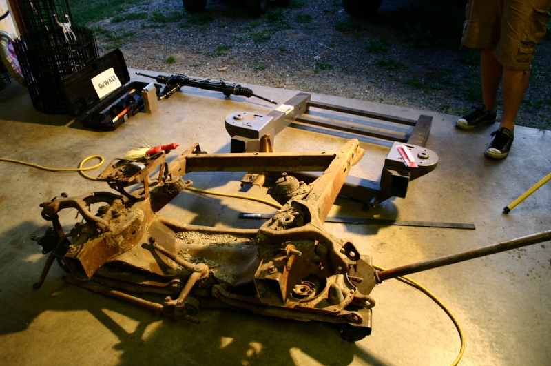
So here it is "sliced off". This was state-of-the-art in 1949 and by today's standards has excellent geomtry, but parts are hard to find and it would be difficult to get disk brakes, air bags, and drop spindles for this set up. So I saluted it and rolled it out of the shop!
So, with the old stuff out of the way, I was able to start positioning the new stub just to get an idea of how it will go on. Alignment at the cuts looks to be perfect.....should make for nice clean and uniform welds.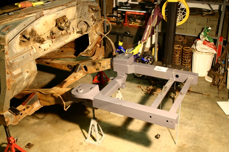
Alignment of the radiator core support also is looking to be dead on!
With the Fatman stub frame and the 429 I'll be putting in, I had to get a rear-sump oil pan otherwise the water pump would be sticking through the radiator. I did a quick location check with the new (bought off cr for $60) rear-sump pan. I think the engine location will be perfect....plenty of clearance for the radiator and plenty of room at the firewall. I'll still need to pick up a bellhousing and position the entire engine and tranny assembly before making any motormounts. 0
0 -
Here's a little more progress. It's kind of a pain to only be able to post 5 pictures in a post, so I have to do it piece by piece I guess. Finally got the stub frame welded on!! Here's some pics and some comentary to go with them.
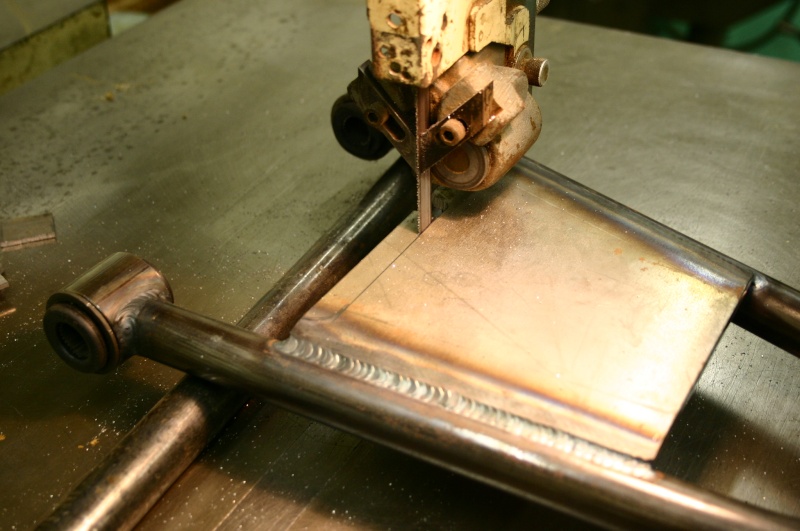
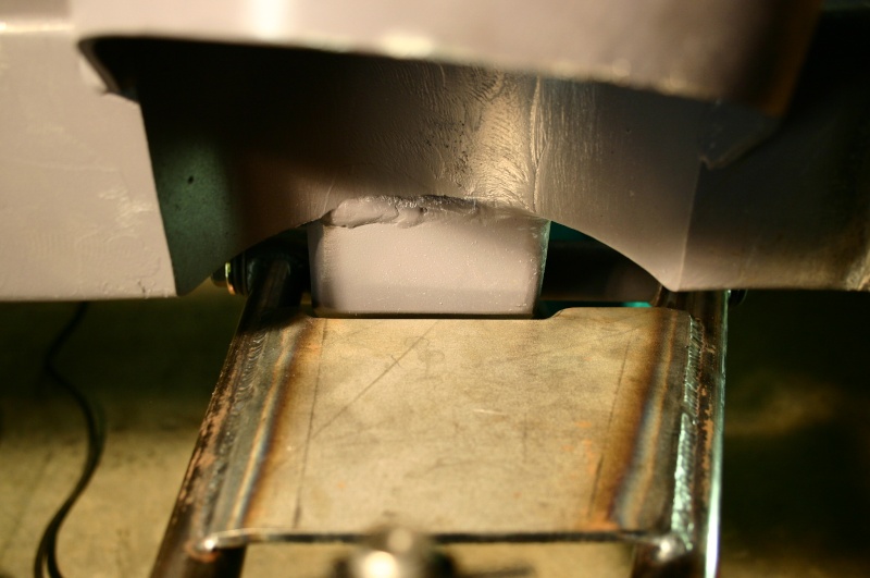
I needed to shorten the frame at the cut location and weld in the "backing plates" to help provide a good solid weld. Here you can see the pie cuts to shorten the section as well as the backing plates (this was done to both sides):
Here's how the frame slides over the backing plates and an 1/8th inch gap is left to fill in with weld:
After re-checking alignmnet with the laser level and plumb-bob, I started laying in the welds by alternating back and forth between the passenger side and drivers side. I eventually had the frame welded completely around but it took a while since I let everything cool completely between welds.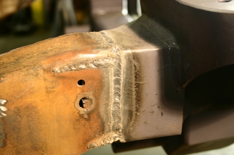
Here's a side view of the stub after being welded in: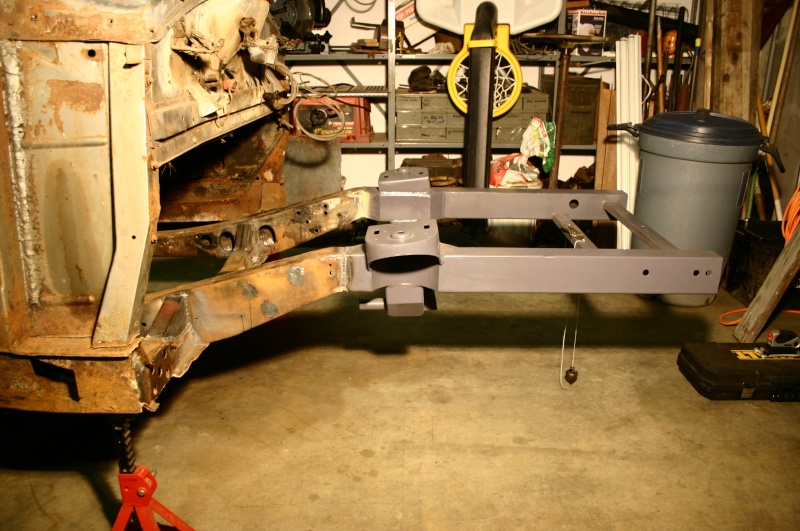
And here's a front view: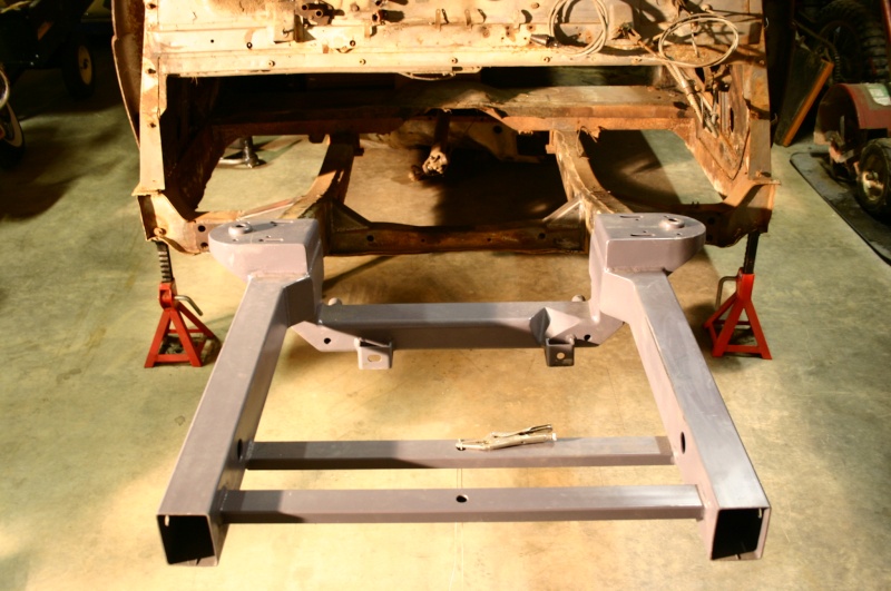
Overall, I'm very happy with the job I'm doing....it pays to take the time to check measurements twice (or more), and prep the weld area prior to welding by grinding and wire brushing. The welds I've been putting down have had excellent penetration. I've had my Millermatic 130 set at power level 3 (out of 4) with the wire feed speed at 50 (out of 100). Now I need to grind the welds smooth and make some final touch-up welds, then it's time for the mustang II suspension!! I"ll keep you posted!0 -
From your initial 'pie cuts', it looks like you had to hammer the the old frame a bit to get it to align with the new stub ends. Didn't this affect the initial measurements, in particular the height?
The passenger side (shown) was about 1/4" higher than the driver's side. The pie cuts shown helped get the original locations level. The new stub was then level as well and the radiator core support was at the right height too. So it all came out good once I got the sides level with each other.
Lee0 -
Hudson308 wrote:As long as everything on the new suspension and mounting points end up where he wants 'em in relation to the original perimeter reference measurements, it'll all be good.
Nice welds... I bet you even calmed Dan's worries.
Yes, I think you're right H308. Of course the "jury is still out" since I'm not actually finished yet") . From what I understand going through all of this is that there are 3 things you need to pay attention to and I think the rest fall into place. They are:
. From what I understand going through all of this is that there are 3 things you need to pay attention to and I think the rest fall into place. They are:
1) Cut the old frame off so that your new frame has it's cross member centered on the original axle center line while leaving a 1/8th to 1/4" gap so you can fill it in with weld. This will put the new axle centerline coincident with the old axle centerline.
2) Make sure the new sub frame is level from side to side with the car (the pie cuts I made corrected this for me. You probably wouln't normally have to worry about this, but my frame was cracked and after welding the crack the frame on the passenger side ended up a little high - eventhough I tried pushing it down while welding the crack).
3) Make sure the new core support is centered on your orginal mark and at the same height off the floor as the old one.
If you pay attention to these critical dimensions, then the bumper holes come out correct and the axle height comes out correct (mine should come out 2" lower since I opted for the 2" drop spindles). I hope it all works out as planned!!
Lee0 -
esfoder wrote:Looks like quite the undertaking!!
Just one question was the origional clip damaged is some way or you just wanted to replace it with some modern metal?
Just wondering looks like a good start..
Dusty
P.S. I have a Hornet with a cracked up front end and was going to replace it with another from a donor car but I'll be looking forward to watching this progress. Might change my mind. The brakes and power steering would be nice..
Hey Dusty, Just at thought.....if you decide to go original with your cracked up front end, you can have anything you want off my old front end. It's missing the passenger side spindle but pretty complete (but crusty) otherwise. Seems like the parts should be easy to find, but part of the reason I went with the new frame stub was because I couldn't find that passenger spindle at any of the wrecking yards that I know of (that deal in classic cars). I'm up here by Seattle.....Let me know!!
Lee0 -
Hudson308 wrote:As long as everything on the new suspension and mounting points end up where he wants 'em in relation to the original perimeter reference measurements, it'll all be good.
Nice welds... I bet you even calmed Dan's worries.
Pretty much
Your work looks good!
If it was mine - I'd still want to fishplate the sides of the frame graft to distribute the load.0 -
rambos_ride wrote:If it was mine - I'd still want to fishplate the sides of the frame graft to distribute the load.
Yeah, me too! I would weld in a fishplate over that seam. This is an area you don't want to minimize on safety.
Peace,
Chaz0 -
Nice work Isirth! I have a stub frame and MII kit in my garage waiting to go into my '50 Pacemaker Coupe. Doc Frommer @Webrodder did one of these on a '52 Hornet. Many and many of these have been installed without a problem, so I wouldn't worry so much. Nice welds and your pictures and narrative are spot on. Nothing like feeling a new suspension underneath you, especially at higher speeds. Nothing against Hudson, but suspensions have improved greatly beyond Hudson or the '50's and now you have it under your rod. And you'll find it easier to lay a late model drivetrain in if you want. Thanks for the good pics, they'll be of aid to me when I finally get to mine. Thought of putting one in my son's '56 Dodge, but not enough money and it's not going to be driven hard anyway. I opted for Fatman's 3" dropped uprights though.
Jay0 -
Looks real good. Suprisingly, it's actually not that difficult of a swap (as long as you don't make the same mistake we made!) and we did end up adding 1/4" plates on the outsides of both rails over the seams. Figured they wouldn't show and made us feel better about safety.
Keep it up, if it rides anything like Uncle J's Pontiac, you won't be dissappointed!0 -
I went with a complete Chry . sub installed like the original was0
-
Another view0
-
Lee,
Just curious -
Any particular reason why you didn't go with Fatman's MII components (one stop shopping, no fitment issues)?
Did you go with Fatman's rack & pinion steering? Is the rack & pinion power or manual?
Hi Rick,
That's a really good question. Basically the FatMan stuff is pretty expensive. I think I saved somewhere between $500 and $1000 by not going completely with FatMan. I've got ~$2500 into the front end so far (~$1000 for the stub and ~$1500 for the components). If I wen't all FatMan I think it would have been close to $3500 by the time you add in the extra money for the 2" drop spindles and the power steering rack. In hind sight, I should've gotten at least the upper arms from FatMan because I ended up having to modify the spring hats on the stub frame to clear my JW Rod Garage upper arms. I'll post some pictures of what I had to do.
Actually if I had to do it all over again, now that I understand how it all goes together, I probably would have gotten the complete shoe-box ford front end from JW Rod Garage ( http://www.jimweimerrodgarage.com/speciality.htm ) and just frabricated the frame at the cross-member myself. It would take a little more effort, but would have saved a bunch more money. I really like the "all business" construction of the JW Rod Garage components and they've been very helpfull on the phone (especially Darrell). The FatMan stub and components would be a good way to go if you're loaded and want to make a lot of progress without as much effort. Just my personal thoughts. I'm going to be ordering the triangulated 4-link kit from JW when I get to the back end!
Lee0 -
stateline wrote:I went with a complete Chry . sub installed like the original was
Wow....looks great Stateline!!! Did you have any issues getting the frame to line up? Were the new frame rails the same width and height as the hudson rails? What model of Chrysler did you use? Thanks for sharing!
Now that I look closely, did you completely remove the hudson cross beam below the tranny??? I've been wondering how well my engine and tranny are going to clear that
Lee0 -
Hudson308 wrote:Yeah, you guys are right. A little extra insurance to ease your worries when you stomp the long one on the right. punching a few 3/4" holes in the plate for extra tack spots wouldn't hurt, either.
Yeah....I understand yours and Dan's concern. Even though it looks pretty crusty right there in the pictures, there's very little rust and the cross beam is really solid. So the way I'm figuring it.....is if the original design was adaquate, then after gusseting the joint I should be pleny strong. The stress in a beam is reduced by the square of the height. So if I doubled the height of the beam in that location, the stress is now 4 times lower. I hope those aren't "famous last words" . If it ever breaks, I'll fish plate it and let you know my original fix didn't work.
I think my '49 was originally a patrol car of somekind. So I think the cracked frame was from a single "overload" event and not from rust. We shall see though!!!!!
Thanks,
Lee0 -
lsfirth wrote:Wow....looks great Stateline!!! Did you have any issues getting the frame to line up? Were the new frame rails the same width and height as the hudson rails? What model of Chrysler did you use? Thanks for sharing!
Now that I look closely, did you completely remove the hudson cross beam below the tranny??? I've been wondering how well my engine and tranny are going to clear that
Lee
Thanks for the complement , the Chry stub is way wider at the mounting point , only about an 1" or so is left of the original cross member outside of the body member where its rivited and welded in. I didnt want the cross member in the way . this modification was spure of the moment , I discovered the fourth 308 I bought was cracked like the other three, I pulled the Chry stub out of the parts shed on a Sat. morning, at 1: AM Sunday it looked like the the first photo, its all together now. the stub is a a 69 NewYorker, only thing I dont like , I gained 1"+ on each side wheel width. having a mopar engine to use already it worked for me . Looks like your doing a great job on yours - I wondered about the Fatman conversion - thanks for posting the progress pics0 -
I bought my Fatman stub and MII kit and it was about $2,450 I think, but that was 4 years ago. I did make the mistake of not ordering the airbags first, so I'll have to deal with that. I also got the power rack and pinion set up. I didn't get lowered spindles as I wanted airbags anyway. I have not installed it yet.
I am interested in that JW Garage 4 link rear set-up, Lee. I looked at their website and the 4 link looks like the Air Technologies kit. If so, it can work with airbags. My headache is the "c" notch.0 -
Stateline, nice chrysler siting in there, and it's sort of a cousin to Hudson. I'm planning on running a '55 Chrysler 331 Hemi in my Coupe. I'm curious if you are going to run headers or stock manifolds? How does the clearance issue look to you?0
-
Hudson308 wrote:Lee;
You may have misunderstood where Dan was suggesting the reinforcement. If we're all on the same page, the suggestion is for a length of 3/16" plate contoured to fit the sides of the framerails, right at the point where old meets new. 6" (or more) of plate welded over this junction might seem like overkill to some, but would sure give you some added confidence when you smack that horse on the backside.")
Hudson308, I believe the write up on Doc Frommer's install on a '52 Hornet did that very thing. Seems like a good idea to me and I planned to do that on my install.0 -
jsrail wrote:Stateline, nice chrysler siting in there, and it's sort of a cousin to Hudson. I'm planning on running a '55 Chrysler 331 Hemi in my Coupe. I'm curious if you are going to run headers or stock manifolds? How does the clearance issue look to you?
Im a stock type guy - dont care for headers, not sure if people understand that the Hudson front frame is completely gone, that Chry. sub completely replaces it .the Chry sub isnt spliced onto the original rails, its complete to the trans. rear cross member and has torsion bars running to the rearcross member too, it super easy to do anything under the car , Im not even using the stock HP manifolds I went with a cross-over pipe ,single exhaust, resonator and big stock muffler . think I'll still have enough power , that is a 440 sitting there .0 -
jsrail wrote:I bought my Fatman stub and MII kit and it was about $2,450 I think, but that was 4 years ago. I did make the mistake of not ordering the airbags first, so I'll have to deal with that. I also got the power rack and pinion set up. I didn't get lowered spindles as I wanted airbags anyway. I have not installed it yet.
I am interested in that JW Garage 4 link rear set-up, Lee. I looked at their website and the 4 link looks like the Air Technologies kit. If so, it can work with airbags. My headache is the "c" notch.
Yeah if you would've gotten the "stage whatever" option with the airbags it would've been more. The FatMan stuff is nice, but just more dough. The JWRG doesn't charge any more if you want drop spindles or power steering (but I think it's rebuilt).
Yeah...the C-notch will be tricky. I like how Lance did it.....there's a link on this forum somewhere that shows a couple pics of his work. There's also a good article in the December '09 issue of Rod and Custom. They still use a leaf spring, but do a good job on the c-notch on a 49 or 50 chev. The Hudson frame is a little different though since it's kind of "nested" set of channels. I've got some good ideas in my head how I'll notch mine.....when I do I'll put more pics on here.
Lee0 -
Hudson308 wrote:Lee;
You may have misunderstood where Dan was suggesting the reinforcement. If we're all on the same page, the suggestion is for a length of 3/16" plate contoured to fit the sides of the framerails, right at the point where old meets new. 6" (or more) of plate welded over this junction might seem like overkill to some, but would sure give you some added confidence when you smack that horse on the backside.
Oh...okay....I get what your're saying. I'll think about it. It probably would be a good idea since I'm not the best welder in the world. I'll take a looks at the link to Doc's install.
Thanks,
Lee0 -
Okay here's some of the things I had to do to get all the JW Rod Garage components to fit on the FatMan stub frame. The parts from both companies seem to be very nicely made and in theory should all bolt together. Mustang II should be Mustang II ....right?? Well, not so fast. Here's some of the things I had to do. Sorry if I'm putting too many picture on here - but maybe it'll be usefull for someone doing something simlar.
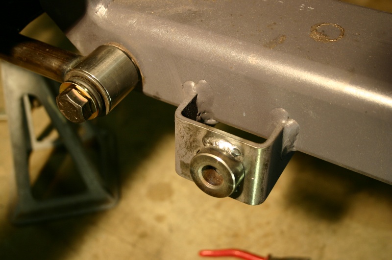
First of all, the lower control arms wouldn't slide on. After a call to JWRG, they said just grind down the bung so the arms can slide on. I carefully scribed a line about 3/16" from the end and started grinding. After grinding I put a chamfer on all corners with a file and slid the arm in place.
Here's a couple pics of that mod: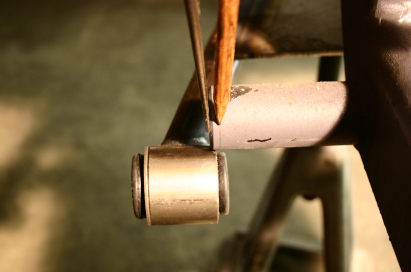
Once I had the arms on, I was checking range of motion, and found an interference between the lower cross member and the flat plate welded on the lower arm to support the airbag. So I scribed the arm and trimmed it out on the band saw. Here's a few pics of that: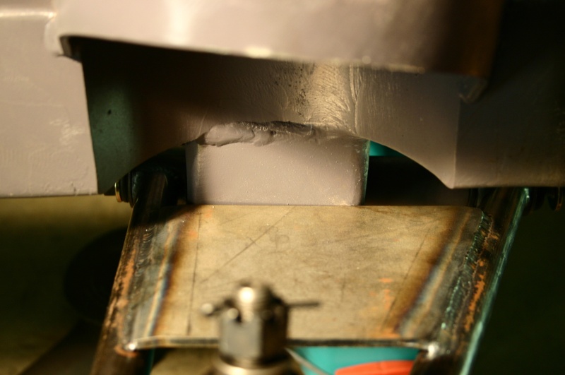
Looks like they only let me put 5 pictures in a single post, so I'll do this piece by piece.0 -
Okay....I'll continue. With the above mods done to both sides, I could now test fit the steering rack.....and guess what.......yep intereference there too. The lower control arm bolts stick out farther forward than the fatman ones would have I'm guessing. Anyway, I wacked off a couple of 1/2" spacers from a very thick walled pipe and welded them on to hold the rack farther forward.
now we have clearance!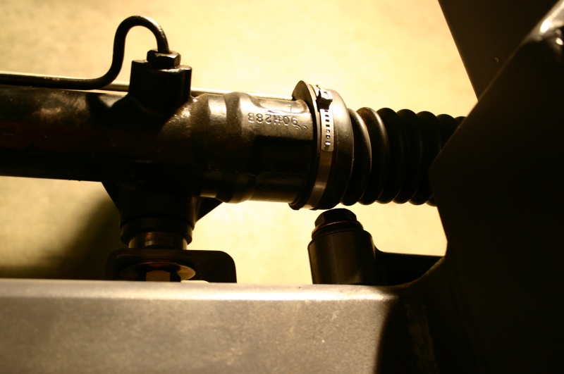
So, next was the upper control arms. A simple fit check revealed that the slots did not extend far enough inboard (toward engine) since I couldn't get the spindle vertical (and axle level) even witht he arm slid as far back in slots as they would go. So, I extended the slots toward the engine about an inch.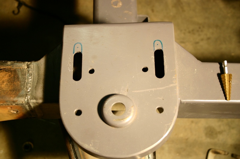
So, now with the upper arms adjusted so there's 1-2 degrees of caster and 0.5 degrees of camber, the upper arms hit the spring hats at full travel downward. So I'll need to do some cutting and welding on them. More later, but here's a pic of the fully assmbled set-up.....minus the airbag supports and the shock mounts.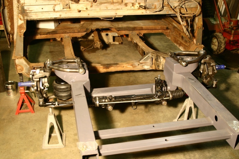 0
0 -
Okay.....following up on the spring hat modification to get around the upper control arm interference. As mentioned in my previous post, the fatman fab upper arms are more rounded and would not have this problem.....but cheep-ass me decided to save some money and get the less expensive (but just as nice) MII components from JW rod garage. Anyway, after talking with their tech line, Darrel said that if you have a manual steering rack that you want ~1 degree caster and if you have a power rack that you'll want ~3 to 5 degrees caster, and 1/2 degree camber with either rack. So, in order to verify how much I would need to cut away from the hat to get clearance, I needed to be pretty precise on the alignment numbers of 3-5 degrees caster and 1/2 degree camber. So the first pic shows how I did this with my laser level and some basic calculations. The rest of the pics show the spring hat modifications needed to get clearance with the upper arm.
Here's the caster settings.....the camber was done in a similar fashion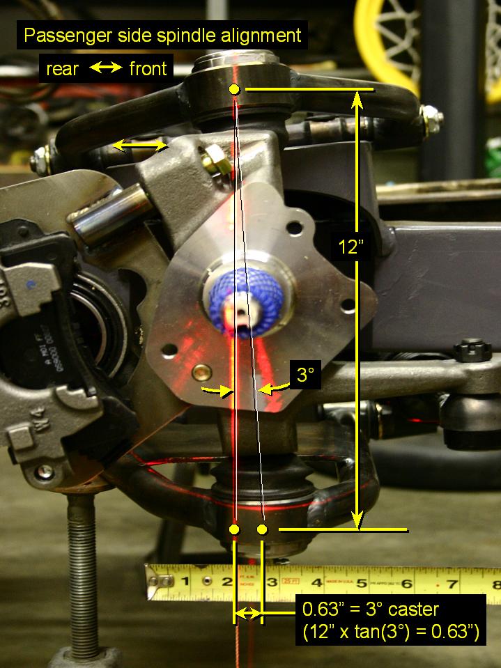
Once the alignment was set, I could mark the hat where it needed to be cut to avoid the interference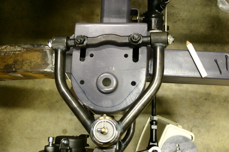
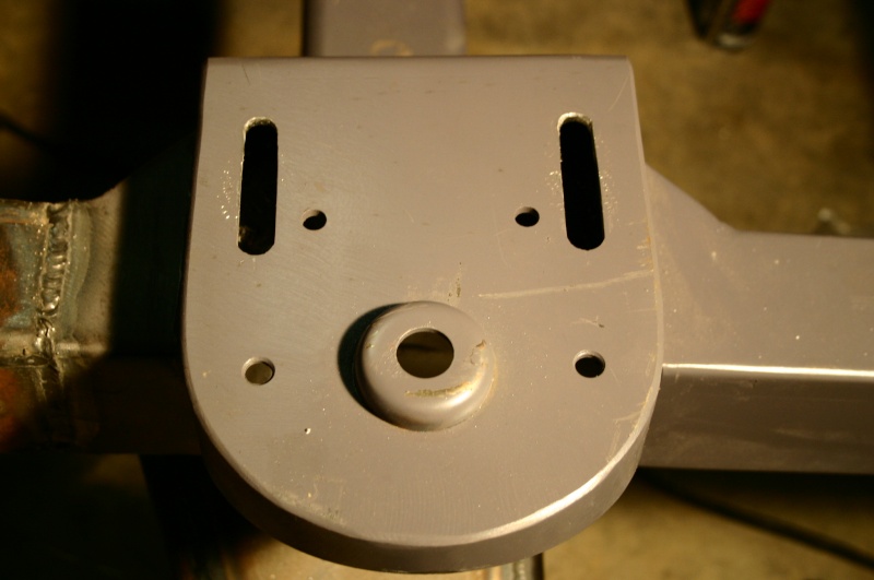
The cuts were made and everything cleaned up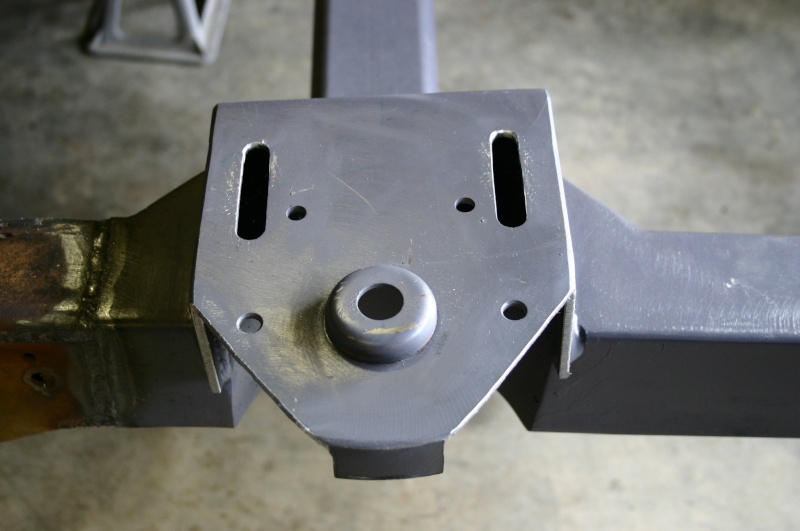
While I was at it, I cut out the spring locator on the underneath side of the hat. I won't be needing this since I'm building a air-bag support pedestal that will bolt directly underneath the hat.....anyway here's the spring locator ground away:
and now it's gone!!!!
Stuck again with only 5 pics per post.....continued on next post.0


This discussion has been closed.
Categories
- 37.1K All Categories
- 121 Hudson 1916 - 1929
- 21 Upcoming Events
- 101 Essex Super 6
- 28.7K HUDSON
- 595 "How To" - Skills, mechanical and other wise
- 995 Street Rods
- 151 American Motors
- 185 The Flathead Forum
- 49 Manuals, etc,.
- 79 Hudson 8
- 45 FORUM - Instructions and Tips on using the forum
- 2.9K CLASSIFIEDS
- 612 Vehicles
- 2.2K Parts & Pieces
- 78 Literature & Memorabilia
- Hudson 1916 - 1929 Yahoo Groups Archived Photos