Project creep, Valve guides, valve job, etc
Comments
-
Its always more difficult doing that type repair in-chassis but your doing a good job and thoughtfully plugging the drain holes to the pan...
0 -
Bill, not only is this post informative, it also shows how the rest of us can post work in a manner that is useful to others.
Thank you very much for spending the time to share how you are taking on this project.
0 -
Thanks for the positive feedback guys.
I've been really busy so I only get a little time each evening to play with this.
After working with the 5/16 x 5" bolt it was just getting too slow for me.
I started looking for various options and it finally hit me. I was trying to locate a bolt or all-thread so I wouldn't have to stop and reset with a spacer half way through.
What I figured out was I had exactly what I needed right on my shelf.
A 5/16-24 x 5" center bolt for a leaf spring pack!! ding ding!! Winner.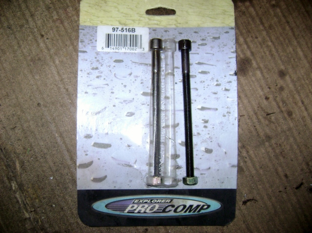
I also received in the mail a couple other tools I order back in the beginning so I could evaluate them for usability.
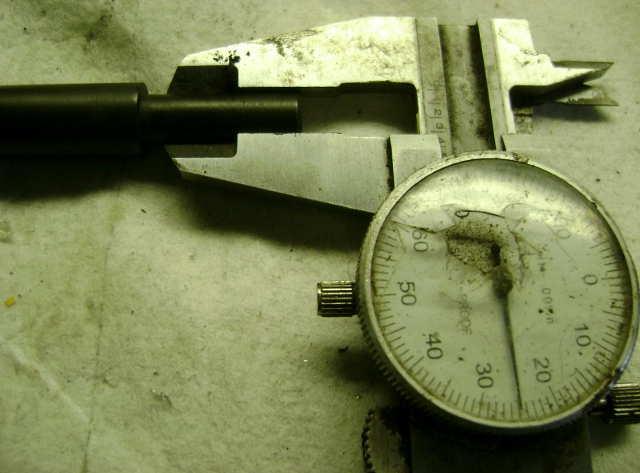
A set of valve guide drivers in 5/16, 11/32 and 3/8. The set was listed for Harley valve guides IIRC.
And a guide driver for an air hammer.
If you look at the pics you will note the tolerances are very different. the guide is 11/32 which is .343.
The one driver measures .340 and the air hammer driver is only .325. And the OD is about .020 smaller.
Making this air hammer driver not a very good choice. The manual one is a much nicer fit for driving them.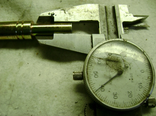
So I removed the next couple guides using this setup. It worked good but is also a little slow with 24 pitch threads.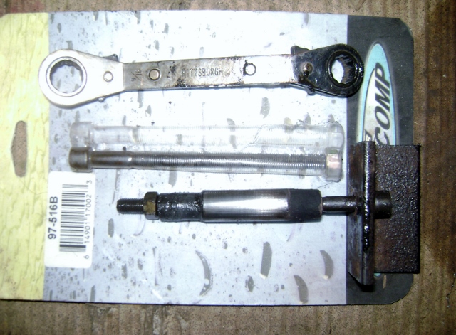
So I says to myself...self, what about that alternate method of removing the lower part of the guide and driving the rest straight down through. Well I replied to myself and was very convincing that I could do that without causing any real damage to the high nickel content block since the guides were just cast!
So this is what I did.
First I took my trusty chisel and gave the bottom a couple whacks. Well that dang thing jumped right off the bottom, clean as you please.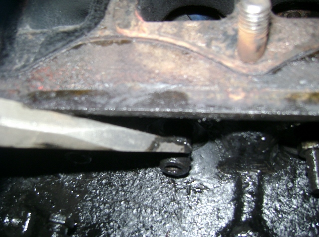
So then I just grabbed my new 11/32 driver and drove the rest right down through. Slicker than hog snot on a railroad track.
NOTE: always stake the guide free with a large drift prior to driving it out or you will damage the driver.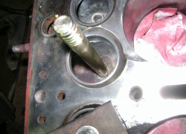
So I finally get to the last guide and what do I find...the wiper motor is in the way. So I had to learn how the cable adjusters worked and then I unbolted the motor and moved it out of the way so I didn't knock it off with the deadly hammer blows.
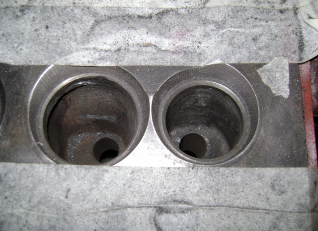
Now that all the guides were out I started to clean up all the surfaces and guide bores.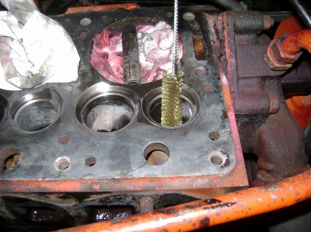
I had read in the manual...yes I read the maintenance manual...that during assemble they mark the block to indicate if an odd size bearing was required.
Well this is the only mark I found, so I assume my crank was all standard when assembled.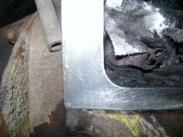
But I also found the remains of a present from a previous owner.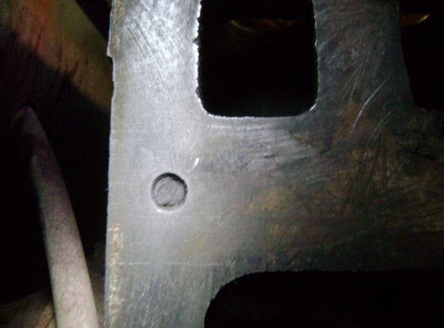
So now I am almost ready for the install!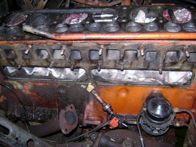 0
0 -
I always cut them off with a chisel and drive them out bottom. Very important to cover things up like you have.
When installing your guides , install the first one to the spec in the manual , then make a stop block out of wood and drive the guide down to the block , speeds up the install.
0 -
Then, when you finally realize that you should have removed the engine from the chassis and torn it down for a proper rebuild, you will see how really really easy it would have been to have driven them out from the underside with a length of cold-rolled 5/8 shafting with a pilot turned on one end. Piece o' cake.
Recall my post of Mar. 19, "There's no place to stop". If you think that crud in the tappet chambers is bad, wait 'til you see what's in the pan!
Frank0 -
I always cut them off with a chisel and drive them out bottom. Very important to cover things up like you have.
When installing your guides , install the first one to the spec in the manual , then make a stop block out of wood and drive the guide down to the block , speeds up the install.
Thanks, No reading ahead in the book. You will spoil the ending. That was for the next post.;)
I took a short piece of pipe and cut it to length.
I found the depths of the guides to be slightly different.
One is .670 up out of the block and the other is .760 tall. So I cut my stop at .900 to start with. I figure I could fine tune once they are close. I also have the measurements from the manual and have set up a way to verify them from the top of the seat down.
So I should be able to get them "close enough for government work:".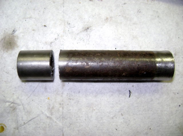
 0
0 -
Then, when you finally realize that you should have removed the engine from the chassis and torn it down for a proper rebuild, you will see how really really easy it would have been to have driven them out from the underside with a length of cold-rolled 5/8 shafting with a pilot turned on one end. Piece o' cake.
Recall my post of Mar. 19, "There's no place to stop". If you think that crud in the tappet chambers is bad, wait 'til you see what's in the pan!
Frank
Hind sight!!
I kind of discussed this a little earlier. I had all intentions of following the advise and order up a complete master kit.
But then, thanks to another member I now have a 54 308 on the way.
So it was either fix all I know is wrong with this one to make it a good runner while I do a complete build on the 308, or order 2 master kits and not have this thing on the road till next summer.
I really want this on the road this summer with the new fuel injection system on it.
So I chose just to repair the 262 and I will rebuild the 308.
I wouldn't say I'm really cutting corners with this engine. As long as it has good compression when done and doesn't smoke, I should be fine. We did drive it on the 4 good cylinders and there was no knocks and no smoke once we burned all the trans fluid and PB blaster we dumped in prior to turning it over.
Everything I am putting into this engine can still be used during a major overhaul. I just will need to buy a re-ring or overhaul kit vice the master overhaul kit to account for the difference in parts.
Still need to drop the oil pump, drop the pan, replace the timing gears and chain, check servicing of all the other fluids, then find out what else I need to rebuild before putting it on the road.
Oh yes, completely sand then acid etch and then prime all body panels since all paint was stripped and then it got wet........In the PNW it got wet. Who would have thought?") 0
0 -
Oh, I wasn't accusing you of cutting corners, I was just poking at you for dreaming that it was not going to be a big job. The 262 is a fine engine and quite frankly don't know why everybody thinks they need a 308. Bragging rights, I guess. Don't forget to have a look at www.vintagefullflow.com when you build that Hornet engine.
F0 -
FYI
If just want a driver for your F/Inj you may not need rings & bearings if there were no knocks or smoke. However cleaning the pan, pickup, and replace the worn timing chain is a must. 262 are good Mtr's....
0 -
Bill Thanks for sharing the experience you are having. As a new person to Hudson engines you are providing inspiration for those who are new to this Hudson hobby. The point of my comment is to give praise to you for taking the route that most who do not have lots of funds will take. Getting the car back on the road is the catalyst that keeps the enthusiasm from slipping away. Being from a "if you break it, you fix it background" the ethos of making repairs versus rebuilding everything just in case, was drummed into me especially hard during my life on the farm. Keep giving us (those who come to visit this forum) the results of your journey to learn what makes Hudson engines tick and what works for you as you repair the problems found. I value your insights.0
-
If I had stopped to rebuild the engine of my Hornet when I first got it... It would still be in pieces now and I would not have been able to enjoy driving the wheels off of it (and the valves out if it ). And now that the engine is almost done at the machinist I have that much more desire to get it done. I like seeing this stuff, I almost went down this road too, Bill. 0
-
Oh, I wasn't accusing you of cutting corners, I was just poking at you for dreaming that it was not going to be a big job. The 262 is a fine engine and quite frankly don't know why everybody thinks they need a 308. Bragging rights, I guess. Don't forget to have a look at www.vintagefullflow.com when you build that Hornet engine.
F
Frank,
No worries, I didn't take it that way at all. I was just clarifying my intentions and reasoning for my chosen path.
I guess the 308 choice is a throw back to our youth, "there's no replacement for displacement" mentality.
In the IH community lots of guys swap out their engine for the bigger 392. I have the same response to them....why. It's only a little more bottom end torque and a lot more gas to make it. It's also a low rpm torque motor but some still try to make it into a performance engine. They end up with neither. On the other side of things, I will be able to finalize a tune for the 2bbl 262 stock engine and then the twin H dual 1bbl EFI on the 262 and then swap in the modified 308 and repeat the tuning cycle. The difference may not be much but it's a way for me to justify it!!
Thanks for the link to your info, quite an undertaking you have going on. Looking forward to seeing the latest update with the new castings.
Farmer/Grimm
Yep, spent many years as a young married serviceman squeezing that nickel to make it last till the next payday. To this day, I have only bought 2 new cars from the lot, and you know who got those.
I would rather put my payment into a maintenance fund for the old stuff than give it to a corporation. But that's just me.0 -
I don't get along with computer stuff very well so I'm procrastinating on the update and photos.........uh, excuse me......."images".0
-
Damn! It did it again! There was much more text that went with this photo but it didn't "go". I'll attempt to repeat:
John F (if you're listening).......I guess I'll have to try your suggestion....if I can make THAT work.
F0 -
I give......it did it again and I'm not going to write another book just have it disappear.
F0 -
Making a little progress.
While my guides were in the freezer getting chilled I decided to clean all the gasket surfaces. The more I scraped, the more I looked at the ports in the block, then I looked closer at the pockets below the valves, then.....project creep reared it's ugly head again.............
I guess I should start by saying there are a few terms in the auto forums that get thrown around a lot. I don't know why but some of them bug me. Like:
Restoration- to return to it's original condition. But today it's used for anything that involves getting an older vehicle to run and drive again. Which has nothing to do with returning it to it's original condition.
Next:
Port and polish- I guess everyone has their own idea of what this means. To me porting in setting it up on a flow bench and grinding and reshaping the contour of the ports to achieve the desired airflow for the desired use of the engine. Most only address the wide open throttle(WOT) dyno run, most HP you can get stuff.
Polish was a term used early on when guys thought that the smoother the surface of the port the better it would flow. They would literally polish the ports to a mirror finish. What they found is the fuel would stick to that mirror finish on the intake side and cause puddling. Which was not desired. So they ended up having to add some turbulence/texture back into the intake port to help keep the fuel atomized in the air stream.
So why all the discussion?
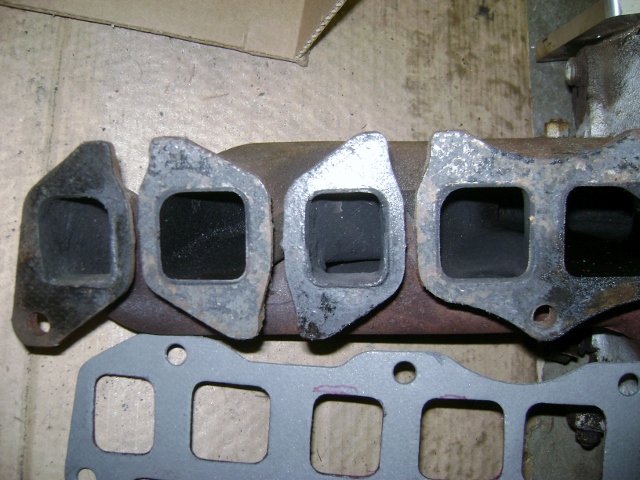
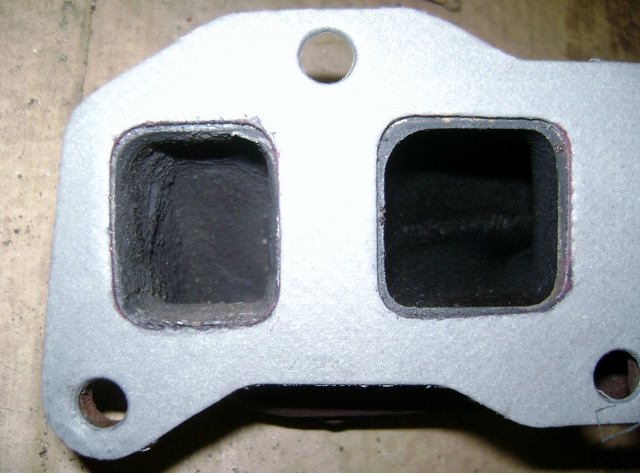
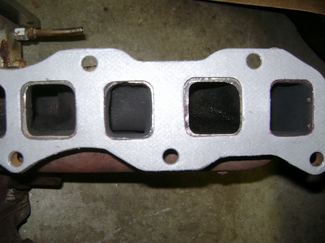
Well, on all my engines I like to perform a simpler "Gasket match", blending of the runners. And I also remove any casting flash from the valve pockets and runners.
To show what I mean, I just couldn't leave well enough alone and had to pull out my die grinder and clean things up a little before installing the new guides and valves.
Most castings a "close enough" for production engines. But there are always some mismatch and some ledges between the manifold and the ports. There are also some tolerance shifts as gaskets are manufactured and then copied later, and then copied again.....So this process helps to match the gasket to the ports in the block/head and manifold.
First I cleaned everything and then masked off all the openings.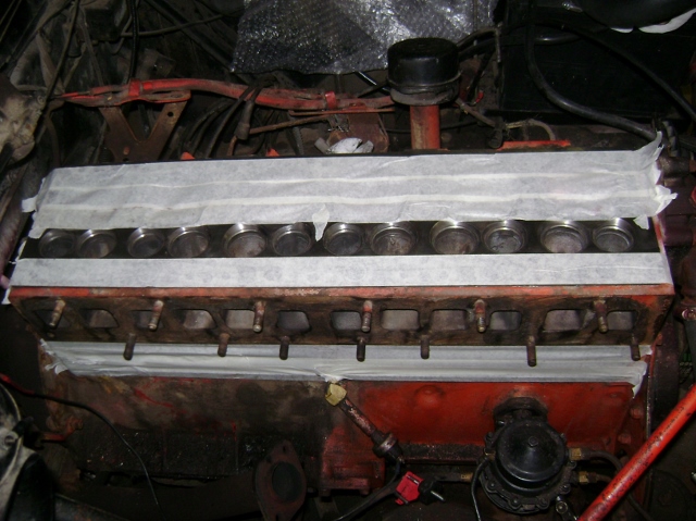
Then I set the gasket in place to show how much mismatch there is.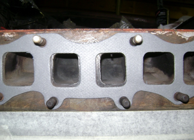
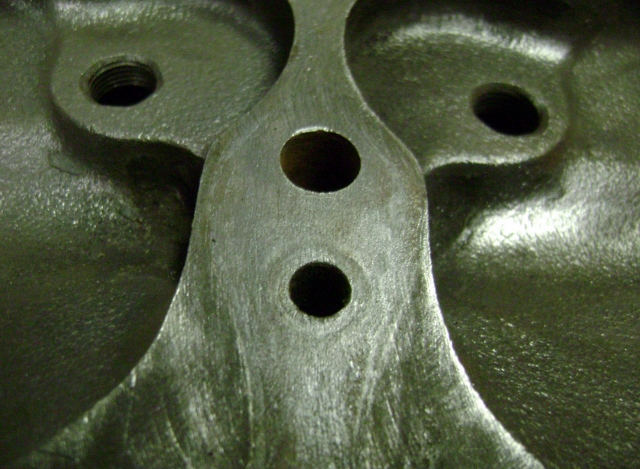
And here is the pocket below the valve.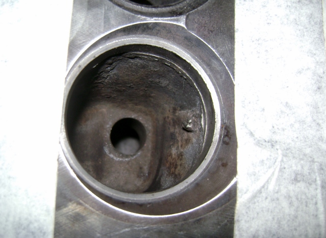
To make it a little easier to show you, I put a line of tape on the head and traced with a sharpe. Normally you use some layout dye and a scribe or anything that you prefer to show a contrast.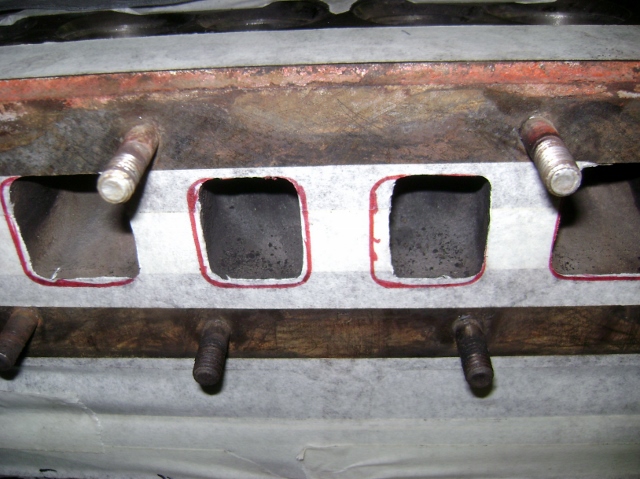
Then I grabbed the die grinder and a carbide bit and cleaned up the extra metal. I didn't get crazy with this motor since it's all stock and not even a complete overhaul.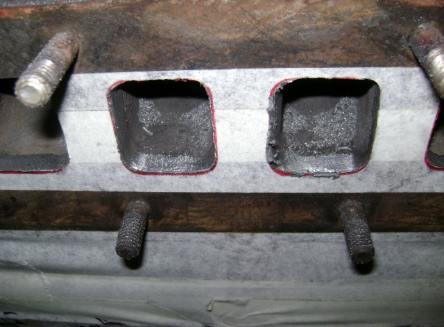
After grinding, I grabbed my sanding roll and blended them in a little, I normally start with the simple porting kit from eastwood.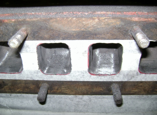
Now I feel a little better and can continue with the valve guides and valve job.") 0
0 -
Damn! It did it again! There was much more text that went with this photo but it didn't "go". I'll attempt to repeat:
John F (if you're listening).......I guess I'll have to try your suggestion....if I can make THAT work.
F
Oh, I understand all too well your frustration on this forums software. I will address that in the other forum.
What I do now is click the "write comment" button, That normally makes the reply text window larger. If any of the editing buttons are visible your not set correctly. They will be grayed out...ooops just noticed mine are visible...dang it,
Click the left mouse button drag and highlight everything and then right click and save....
Now click the write comment button and watch it all disappear.
go to the top part of the text window and right click the mouse and select paste.
whew, it's back.
I copy every post I type now before I hit the "post comment" button.
If not I am very pissed.
You can also use the <> button on the tool bar to do the same as the write comment button.
But NEVER hit the post comment without highlighting and saving all you typed.
A good hint is if you don't see the save draft msg about every 30 sec on the lower left...your text is not being saved!!
Hey frank...will my head fit in that surfacer?
manifolds?
HMMMM nice.
Let me know what time dinner is! I have to schedule the ferry.0 -
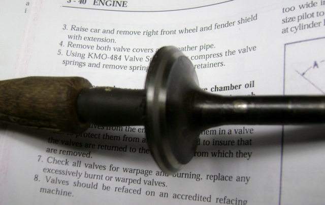
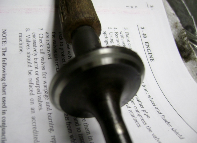
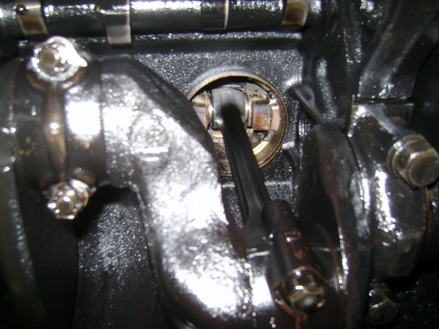
Back to the guides and valves.
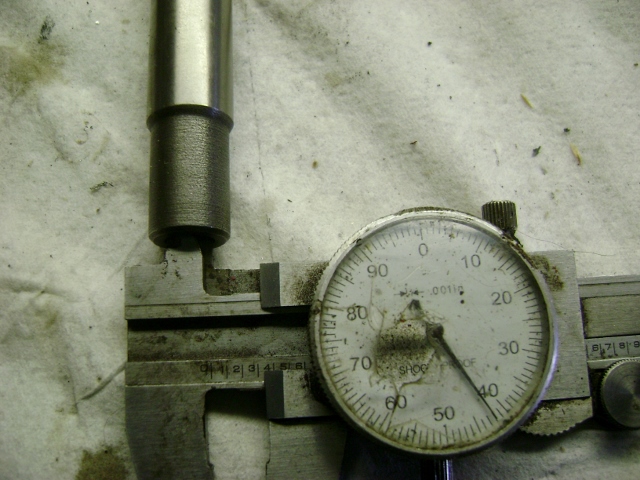
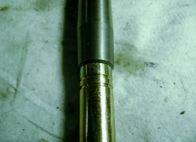
Here's the tools I used to drive the guides into place. The 11/32 driver, a washer that fits exactly over the guide tip. I used a 5/16 flat washer and cleaned up the inside with a small rat tail file to fit.
And my spacer. I cut it down to .800 long for a starting point. better the guides be a little high then to knock them in too deep and have to pull them back up.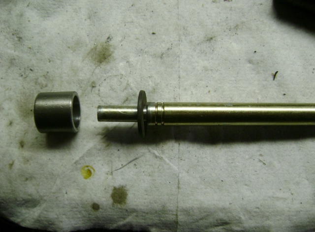
Guide and driver tools in place. Dive them down till the washer seats on the spacer.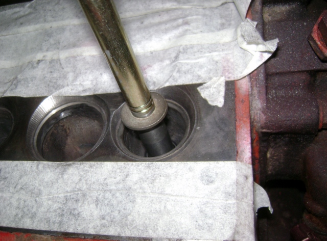
Guide flush with spacer.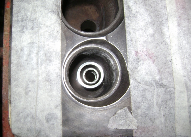
I used my .080 thick ruler and a platform for measuring. That way I could simply add it to the specified measurement. 1 3/32(.09375) + the .080 for the exhaust and 1 7/16(.4375) + the .080 for the intakes.
The ruler has to set on the top of the valve seat.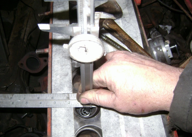
I adjusted the depth as required. The exhaust needed to go down a little but the intakes were right on the money. See my earlier post when I measured for the spacer thickness.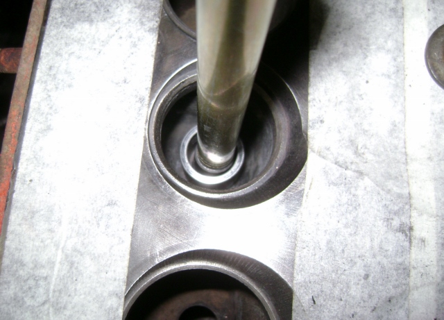
0 -
And now for the valve job.
Many people have their way of doing this also. I'm not saying mine is right, just the way I do it.
For me all valve jobs are 3 angles. Full race jobs can be many more.
But I use a 45 for the seat, a 30 for the top and a 60 for the center. There are variations to this like a 44 for the seat, 15 for the top and 75 for the center. But the basic idea is to get the seat width correct and get it located on the valve in the correct spot.
The service manual has the specs so I won't repeat them here.
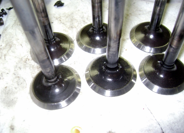
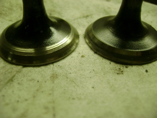
Exhaust valves.
I got them all cleaned up and surfaced the face. My original exhaust valve stems were worn almost .010 so none of them were really useable. I picked up another set of used ones on ebay and the stems were only worn about .002. So I used them. If I rebuild this motor later it will get all new valves. I lightly hit the seat with the 45, came back and touched the top with the 30 and the inside with the 60 just to give a nice even circle seat. I then used some fine lapping compound and seated them in. On the first pass they looked good enough so I decided just to leave them where they are. You can adjust the position on the valve by alternating your cuts with the stones. Use more top 30 and less bottom 60 to move it down or vice versa.
My personal taste is to have them a little thinner with the top just about where they are.
I was pleased given all the changes I made and using used valves.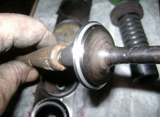
This is why I lap all my valves. On one of them I found a flaw in the surface. So I took it back to the grinder and faced it a little more to remove the flaw. If ran like that it could have led to an early burnt valve.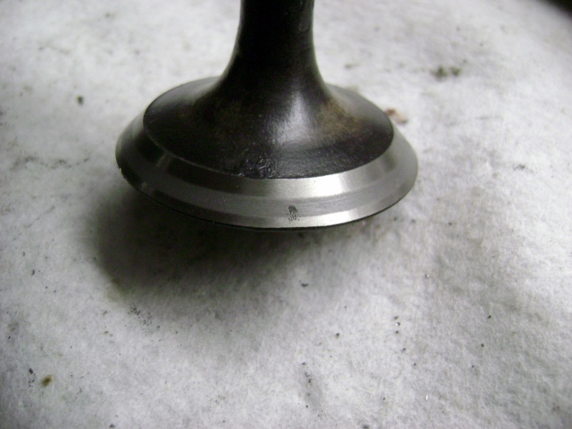
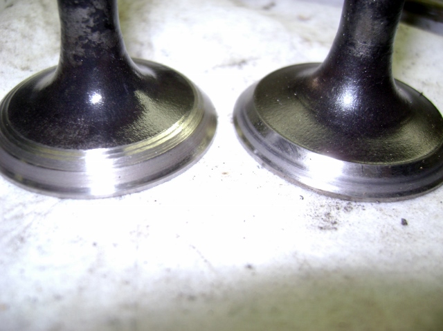
Intakes got the same treatment and turned out just as well.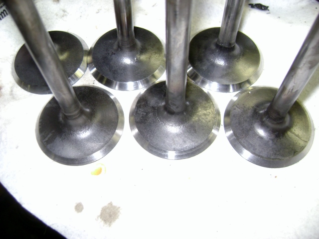
All done with that part!!!!!!!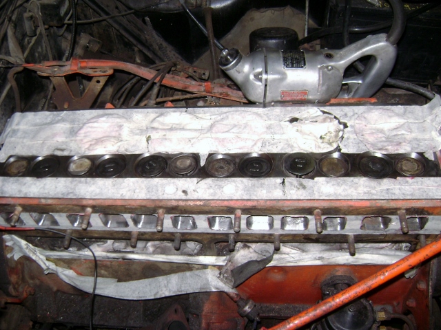 0
0 -
They are a little thin. I may have a lead on some more and if they are better I will swap them out before the head goes on.
Other wise...I guess I take my chances and get what I deserve.
0 -
Frank
Sent you a PM
0 -
I'm enjoying reading this thread, it is very interesting and helpful to others who don't do this sort of work every day yet on occasion need to do so. A couple of points I noticed:
- the intake gasket looked badly mismatched to the block ports. But how well did it match to the manifold ports? Usually all three pieces need to be matched together, then a couple of small dowel pins placed to exactly locate the inlet manifold for a perfect fit.
- The underside of the valves is just begging to be undercut to improve flow, ie the inside edge of the 45 degree face cut.
0 -
TP8- I don't do this everyday either. That way I can still enjoy it in my spare time.
It's also why I try to do the write ups whenever I do a job that's not the standard maintenance items.
I figure if I learn how to do it, others can. And it's good to get feedback along the way. Someone always comes up with a better mouse trap!
Good questions on the manifold gaskets. I haven't got that far so I didn't post yet. Still need to clean them up and probably take them down and have them surfaced to make sure they are flat.
But it's the same song, different verse.
The ports are just as badly mismatched as the block was.
You can see the carbon build up where the gasket wasn't.
As for the alignment, I don't think on the big six it would be an issue and the pins would not be needed. The manifold already sets on studs on the outer mounting holes and tolerance between the gasket and studs keep it in place pretty well. As long as the manifold also sets centered on the studs it will be close. Simple piece of tubing with the end ground to a taper can be used to keep the manifold centered on the studs while snugging the nuts down.
If I were building a performance engine then all the little things can add up. With the valves out you can test fit the gasket and manifold and use a wire or scribe down thru the port to verify the alignment before final assembly.
Multiple angles on the valves and seats are a definite performance flow improvements.
maybe my 308 will get that.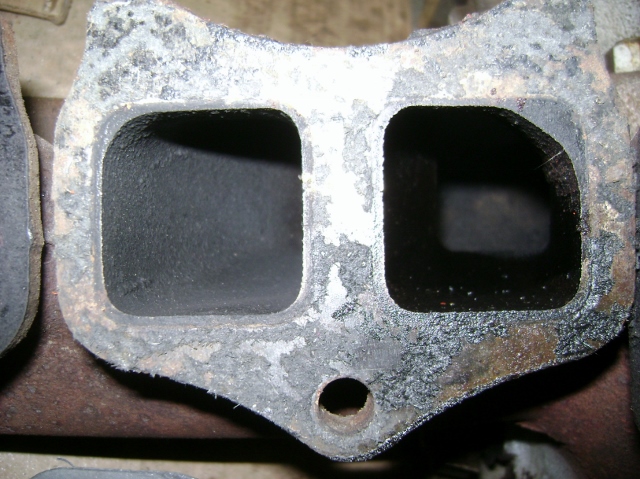
 0
0 -
I hope those used exhaust valves have enough margin on their edges to not curl/ warp. Hard to tell in the pix, but They look a little thin on the margins.
Well if I don't replace the valves, I took your comment to heart and made my 1.56 OD exhaust valves 1.55 OD exhaust valves. Just to give a little more margin.
Since the contact was a little low on the valve already, no harm no foul on these.
As long as the valves weren't sodium filled I should be fine!
The valves are all lapped in and plenty of meat showing on all edges.
Thanks0 -
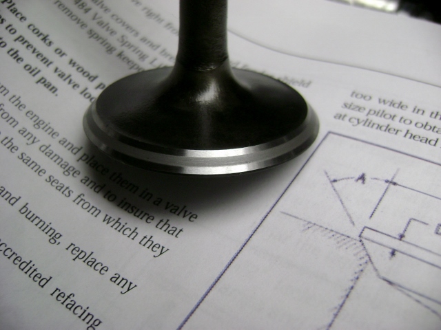
I ended up with another set of valves in better condition so I cleaned them up and lapped them in.
Since I had the valve grinding machine running I decided to show what TP8 was referring to by back cutting on the inside lip of the valve face.
This is done on performance engines to help with flow but can be done on any engine. But if your paying a machine shop by the hour, it may cost more than the actual gains justify.
I did a simple 45* facing on the valve, then ground a 30* and then finished with a 15*.
I just did a light grind on this valve since it was getting dropped into my engine.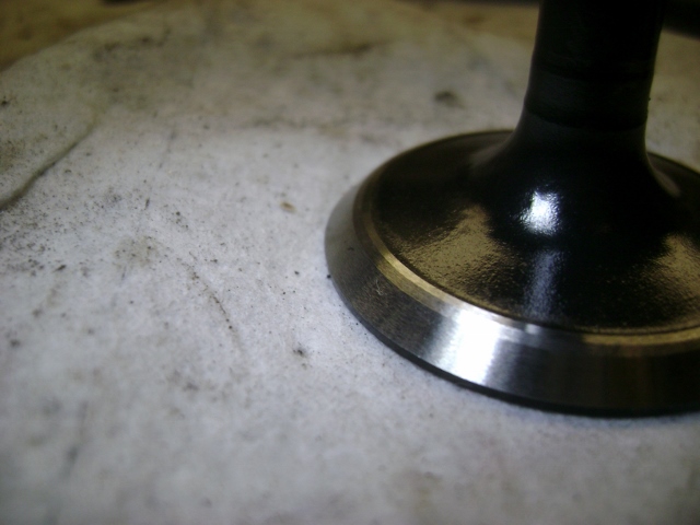
Once they were all lapped in I grabbed one of the old valves and did a little more aggressive cut.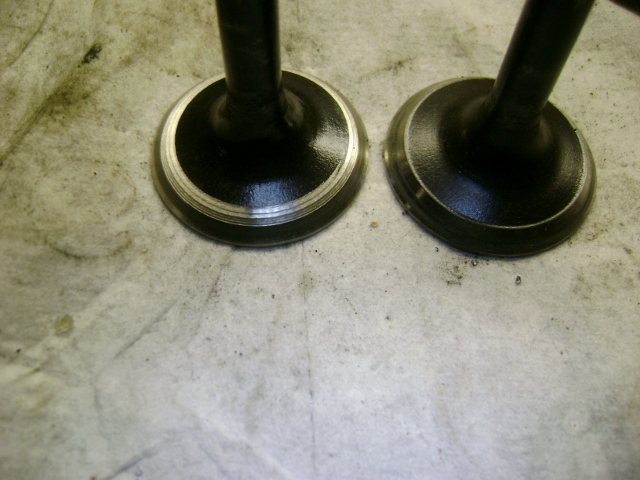
 0
0 -
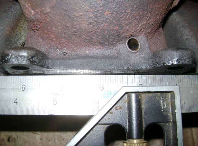
Started cleaning up the head. I didn't even think to do the dye penetrant test on it for cracks. But it's out at the machine shop getting surfaced along with the manifolds.
I had about a .020+ gap at the center exhaust ports so I figured I better do it now instead of having to pull it back off later.
I measured the thickness at 1.995 so it must be close to factory.
I told the machine shop not to be afraid to cut it thinner.
The cross hatch was gone in areas so it needed a good surfacing.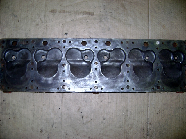
I pulled the hose fittings and the thermostat housing. Not surprising, there was no thermostat. Some thing else to look for.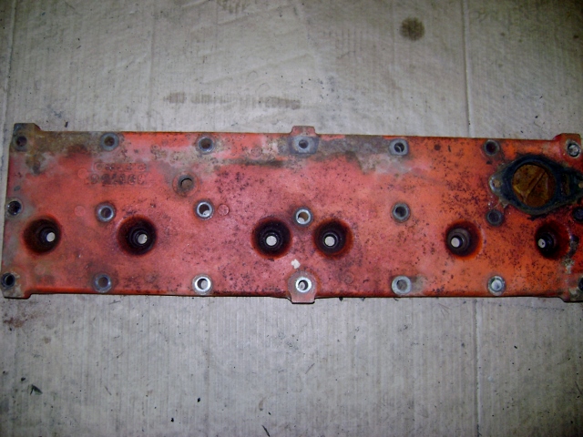
I used a straight edge on the manifold. Hard to show in a pic.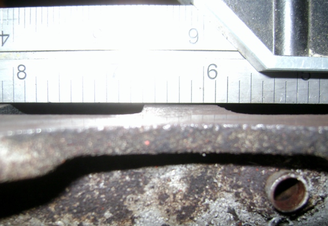
 0
0 -
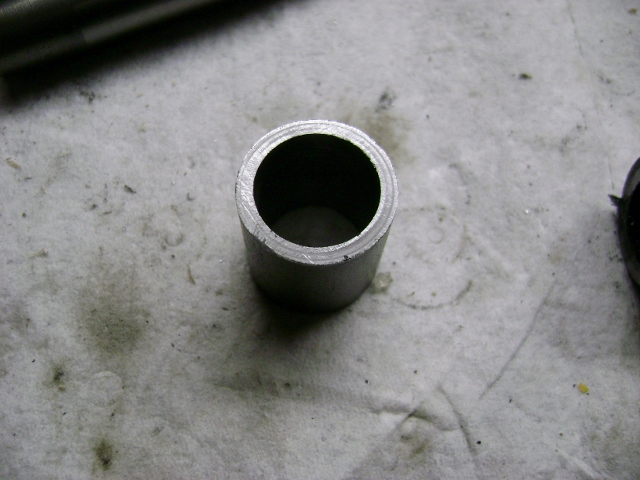
While the manifolds and head are out at the machine shop I decided to keep digging.
I dropped the pan to do a little inspecting. I still need to pull the front cover to do the timing chain and gears.
But the more I dig the more the hits just keep coming.
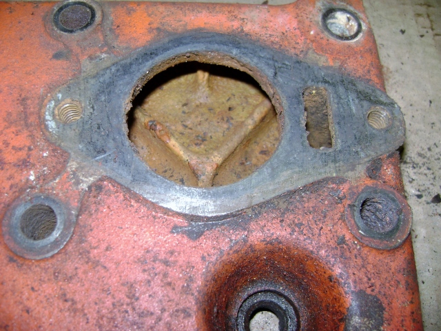
When I dropped the pan I found this.
It doesn't look like it was leaking too bad but still gave an uneasy feeling. Was it sucking air and running with low oil pressure?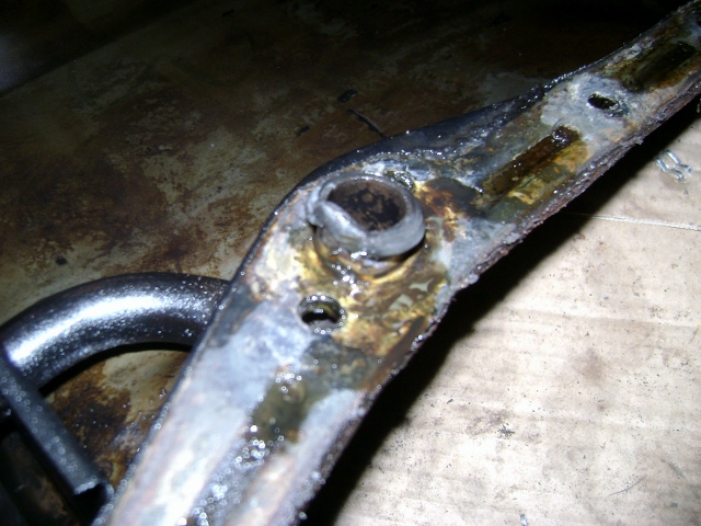
The bottom of the pan didn't look too bad but I haven't sifted thru it yet.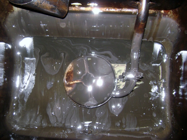
Rear main seal looked like a little seep but no drips. I haven't looked into how hard it is to replace the old rear main seal with the crank still installed?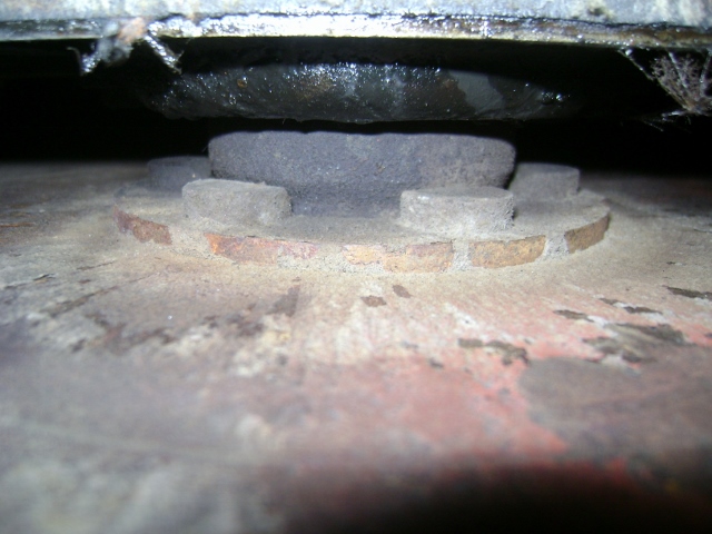
But then things take a turn for the worse.
I wanted to get a good look at the oil pump and distr drive to see where all the slop was since I just bought a new gear. It was mentioned back in the beginning that over time the cam teeth will wear and the drive gear will be fine.
ARGGG
Well that seems to have come true for me.
The cam teeth are completely knife edged and the drive gear looks new.
So guess what else I get to replace!!
I just pulled a 306344A from my core 56 308, so it looks like that cam is going in this 262.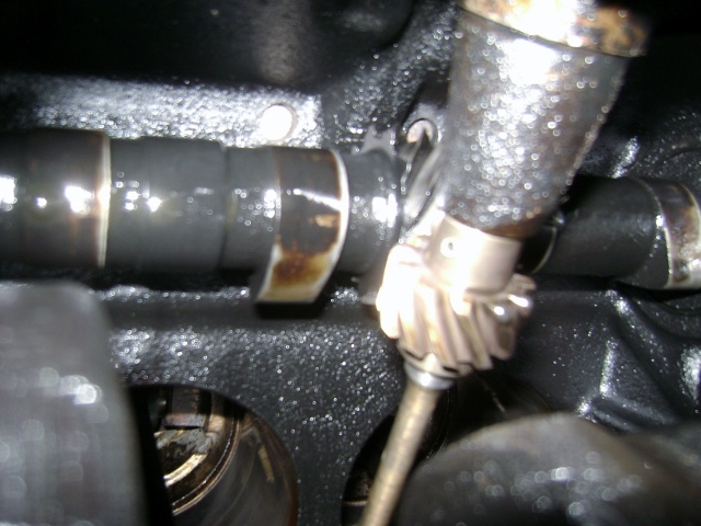
The next thing I noticed, and it may be perfectly normal, is the small end of the rods are ash colored. I know these are full floating pistons and pins with bushings so my concern here is proper oil vapor getting to the pins and bushings for lubrication.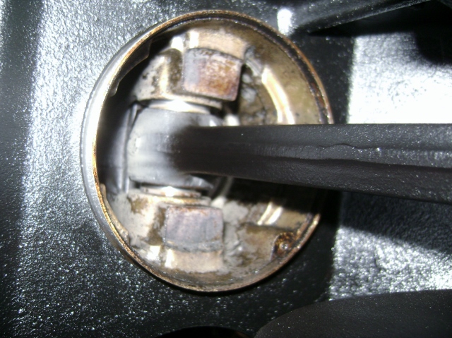
So I am now about 6 bolts away from just throwing up the white flag and yanking the block.
That way I can flip it over to do the cam swap without worrying about lifters dropping out and maybe do the rear main seal and it will give me a chance to inspect the cork clutch. Oh my I really hope that's ok!
Thoughts?
Some happy thoughts would be nice! 0 -
Happy thoughts? Hang in there, Bill. You're doing fine and good, thorough job. You know it's almost always like this, that "project creep", that is.A couple of thoughts:1. Your valves look good, but couldn't follow what the extra relief cut on the bottom side was for? That wasn't necessary, was it? Fill me in . . .2. I'm sure you won't need it, seeing as how your head was only a shade under 2", but don't let the machine shop shave it more than .060". More than that, the Hudson Heads have a tendency to warp.3. As far as the oil pressure goes, keep in mind that the Hudson engine runs on VERY low pressure, from the factory. Can't remember off of the top of my head, but idle is like 20psi. They're not designed as high pressure engines from the beginning. Still, it does look as though that engine has had circulation problems. It's a good thing you are going through the whole thing . . . or "6 bolts away . . ." Heck, you're this close, I would go ahead and do the rest of it. Go from project creep to project leap. I think the effort will pay dividends later, rather than immediately.4. What Ken said about the cam. Common 262 problem, from what I have learned. Like Doug says, "It won't fix itself".0
-
By the way, thanks for posting all of your findings. I'm sure many are enjoying and learning from your posts.0
-
Thanks Ken.
I remember spending an hour or so looking thru every page of Doug's pics.
I also notice his 67 Corn binder. I have 1 (actually 3) like it but the crew cab version. And a dump bed version and ...well it's an addiction. They're like rabbits. If you park them close together, they multiply.
My goal of driving this thing this summer is "creeping" away from me!0


Categories
- 37K All Categories
- 119 Hudson 1916 - 1929
- 21 Upcoming Events
- 100 Essex Super 6
- 28.7K HUDSON
- 595 "How To" - Skills, mechanical and other wise
- 995 Street Rods
- 151 American Motors
- 185 The Flathead Forum
- 49 Manuals, etc,.
- 79 Hudson 8
- 45 FORUM - Instructions and Tips on using the forum
- 2.9K CLASSIFIEDS
- 612 Vehicles
- 2.2K Parts & Pieces
- 78 Literature & Memorabilia
- Hudson 1916 - 1929 Yahoo Groups Archived Photos