Project creep- Part 2. engine bearings, cam, head, broken bolts, PCV
Here's the link to part 1
http://openforum.hetclub.org/discussion/165555/project-creep-valve-guides-valve-job-etc/p1
Lots to catch up on!
Comments
-
When I left off I had pulled the engine to do the seals and the cam swap.
The original cam was the 300022 and the distr drive gear on the cam was almost worn off it. The teeth were to a knife edge.
So I pulled a cam from one of the 308s and it's the 306344A.
I also pulled the lifters from the 308.
So I started to remove parts.
First the balancer, timing cover, gears, chain, front engine mount...etc.
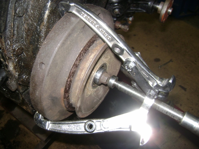
I loaned out my large puller so I had to make due with my small HF puller. It worked but barely.
I started with the center bolt still in till I broke the balancer free. It was only screwed in a couple threads.
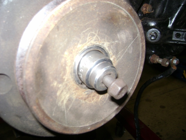
Once free then I switched to a 15/16 socket in the hole and a bolt and washer in the socket to have something to pull against.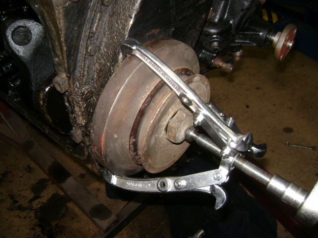
No surprise, this was about the worst chain stretch I have seen. I'm surprised it didn't jump a tooth.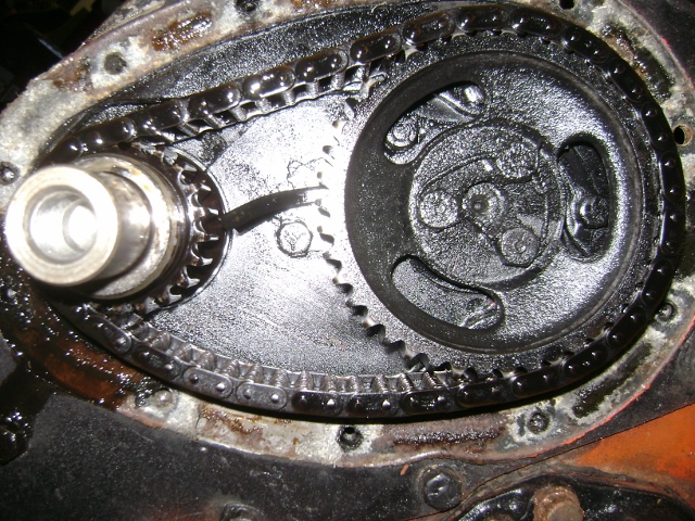
The lock wire actually installed in the cam bolts.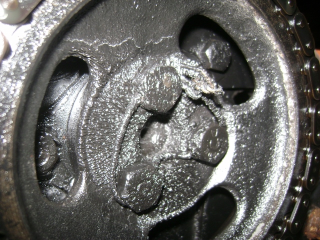
Removed both gears.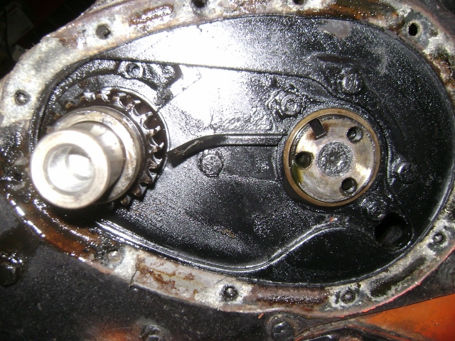
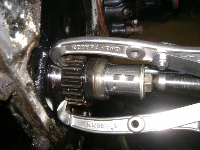
And I will need to address the galled crank with some polishing.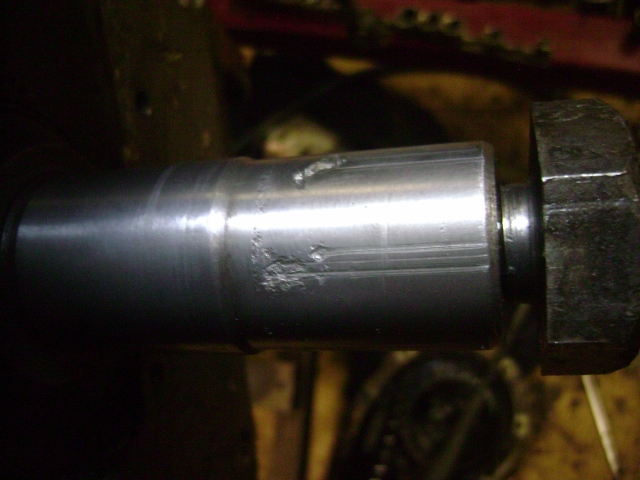
0 -
Next up was to get a look at the bearings.
So I started with a rod bearing.
This is #2.
At first look I thought, heck, the babbit is still on the bearing so it can't be that bad.
I also noticed the copper color behind the bearing insert?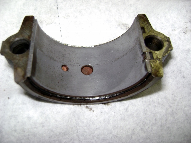
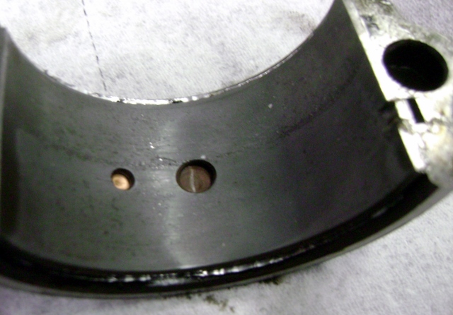
The crank didn't look too bad. I could feel the wear difference where the oil hole is located. I guess with a bypass system that's to be expected.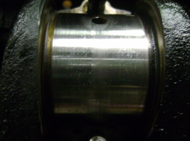
So popped out the shell and found the date stamp.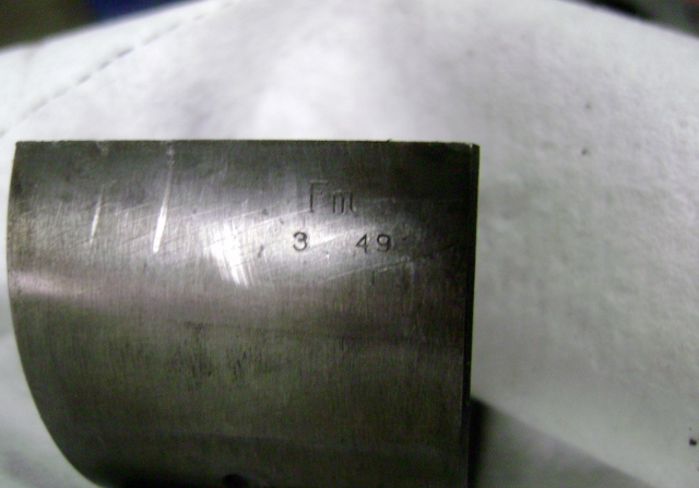
And I guess the clearance was hand fitted at the factory or some shop tightened up the clearance along the way with some shim stock behind the bearing shell.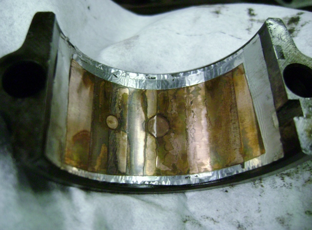
So now I have another decision to make on this 262. Do I now remove the crank and have it turned for undersize bearings, then do I pop out all the pistons and have it bored so it's all new, or do I just plastigage the clearance and bolt it all back together.
OR
grab my core 308 and do a complete rebuild on it and just cut my losses on the 262?
My project just keeps creeping!0 -
FYI
Well we know someone was in there and tried to tried to tighten up the clearance the wrong way then botched the pan installation on the way together........
Suggest 'Mike the Crank' then if just slightly worn but not not out of round, install available 'undersize' Brgs...
0 -
Thanks for the input guys.
It doesn't matter the make of vehicle it is...the PO-previous owner mods always seems to bite us.
Well I started out using the plastigage on the bearings.
Things were looking pretty good.
The rod cap I pulled gauged at about .0015.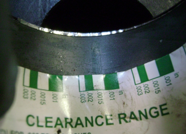
Then I pulled the front and rear main caps.
The mains also shim tape. The front gauged at about .0025 so a little looser.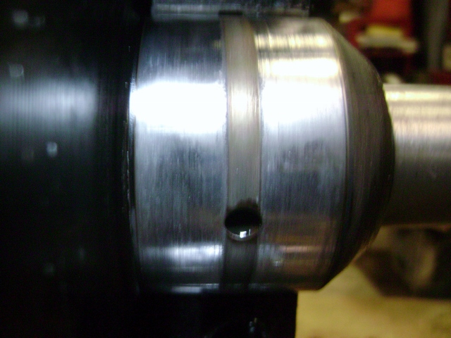
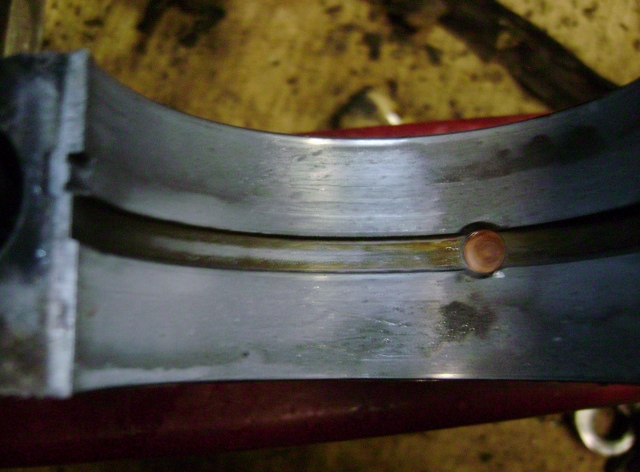
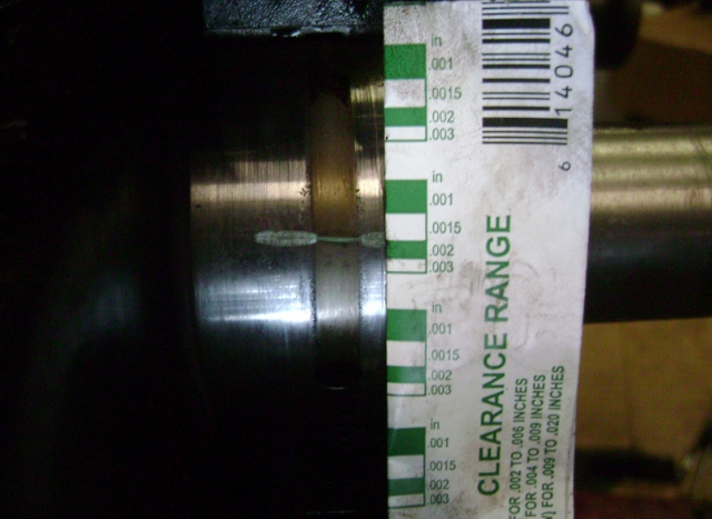
The rear main looked a little worse, like it had some heating or something. It also looked like some moisture got on the rear main seal surface and there are small pits in it.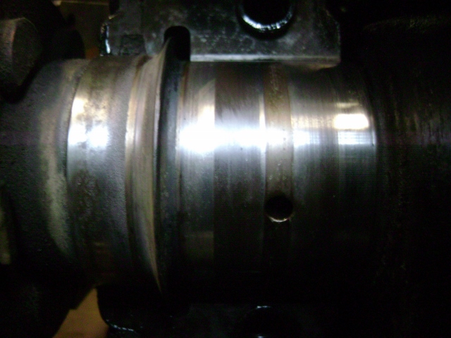
So then I grabbed my dial calipers and measured the crank journals.
The mains look to be standard, right at 2.49x
But the rod journal measured at 2.110+-.
Which if I read it right, would put them at .015 under.
I pulled the #4 rod and it measured the same.
?????
Strange since the bearings seem to still be standard. There's about 3-4 layers of the shim stock. It appears to be .001 thick.
So now my concern is...
If I have the crank turned, are the rods out of round and now they need resized?
I am seriously considering just pulling the plug on this 49 262 and grab one of the wide blocks and do the complete rebuild on one of them. I hate to write off everything I have done to this 262, but if I continue it's a complete rebuild. If I commit to that then is there really a need to build one of the 308s?
Are there any big advantages of the wide vs narrow blocks, one way or the other?
----------------------------------------------------------------------------------------------
But on a good note, or bad depending on how you look at it.
I got my head and manifolds back from being surfaced.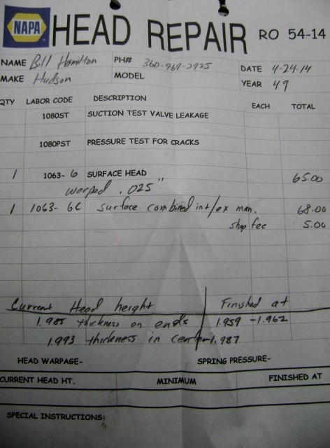
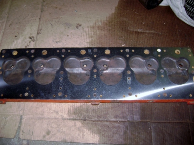
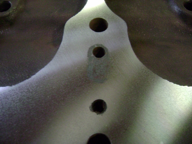
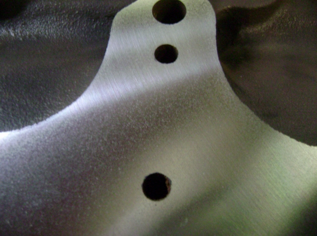
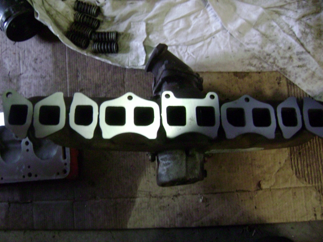
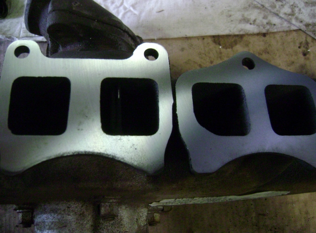
Did a quick search online.
The shim stock is still avail!!
This could save me lots of money.
http://www.deckwartaperedshims.com/
Man, this thing is wearing me out.0 -
When I was in trade school in the 60's , shims were an accepted practice , and a lot of time was spent on the proper measure and installation. I used them on a worn Olds V8 , raised the oil pressure , and the engine took a lot of abuse. I worked at a construction equipment rental/sales place and shimming was a standard practice.
Some of these Hobby car engines are over done , considering the amount of use they get.
A lot of lawn mowers get more hours on them in a year than the cars. I see nothing wrong with what you are doing. Set the clearance's , clean and seal the engine , install the cam and timing chain , and enjoy your car. You seem to have enough common sense to know when something would not be reliable for your intentions.
I had a 49 with 262 and OD for many years. I preferred it over the many Hornet engines I had , Better gas
mileage , smoother , and it would do 100 MPH. I think Hudson got it right the first time.
0 -
FYIIf I read correctly, I would put in a new set of Std Main's with a new set of .001 Rod Brgs then install the Neoprene Mopar rear seal and the Timing Chain.... Personally, I would Not use shims.
There is No advantage between a narrow and wide Block 262, However, there is a big Power advantage when building a 308.
If your just building a Driver Test car for your Throttle Body, and not building a Racer, stay on your same course....A 262 will easily keep up with todays Interstate Traffic....
0 -
After much thought and discussion with the son I am going to continue on my original path.
This 262 will get cleaned up and put together like it came apart.
The rod journals were .015 under, not .0015 so I guess I could do a set of .010 under bearings with a shim. But then if I'm doing that and not doing it the "correct " way by turning the crank to .020 under, then I might as well just leave the old bearings just like they are.
It did run. But I was so excited to get it running and driving that I really didn't listen for piston slap or bearing noise.
So I removed the crank so I could clean and install the rubber rear main. I was already ahead of you on that one Ol racer!
I decided to surface the lifters since they were pretty worn. (must have been running the new fangled oil in it)
And I started to clean the block up and drill out the broken studs and bolts I found during disassembly.
Here's the lifter before.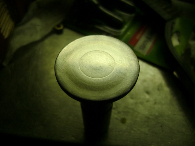
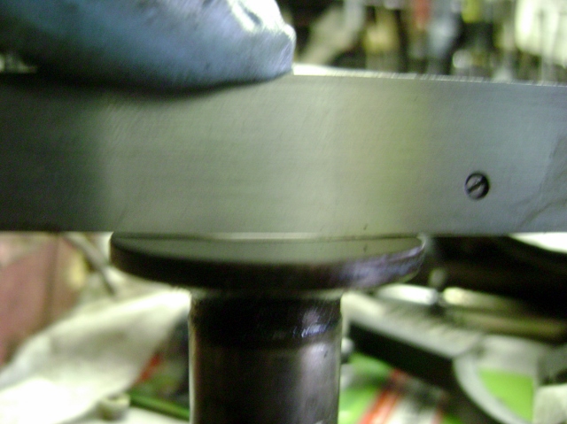
And almost flat again.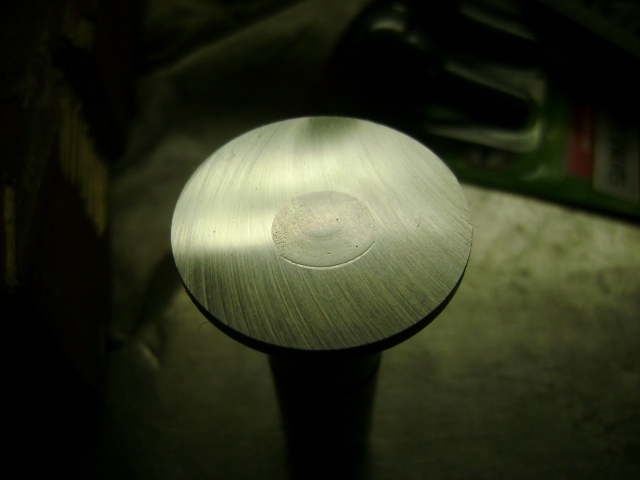
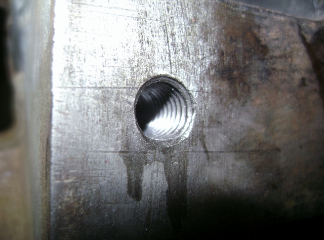
For the broken manifold stud.
I started with my reverse cut drill bits and worked my way up to 1/4" with no movement.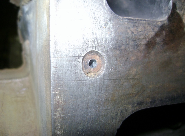
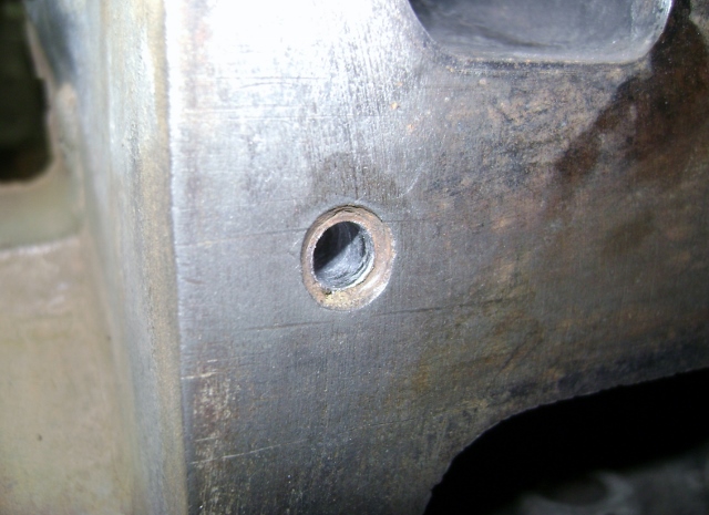
So then I tried a 5/16-18 tap to see if it would grab it.
Still no movement.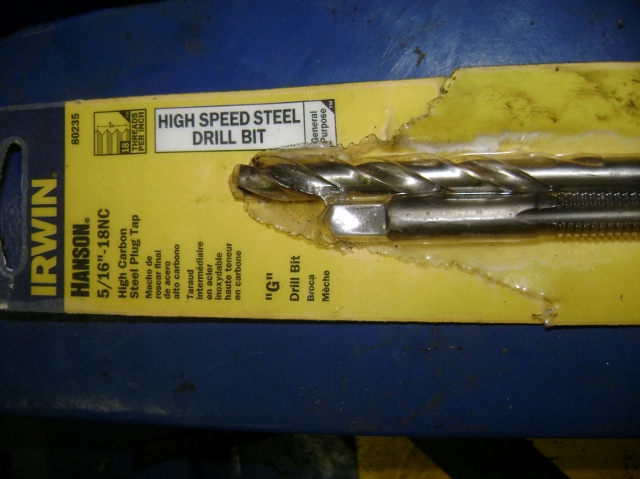
So I stepped up to my 3/8-16 tap and drill and was able to peel most of the remaining threads right out.
It helps if you are centered in the hole so the threads are all that is left of the old bolt/stud once you get that big in diameter on the drill.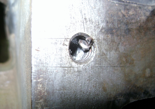
Then a clean up with the 3/8 tap and all was back to original.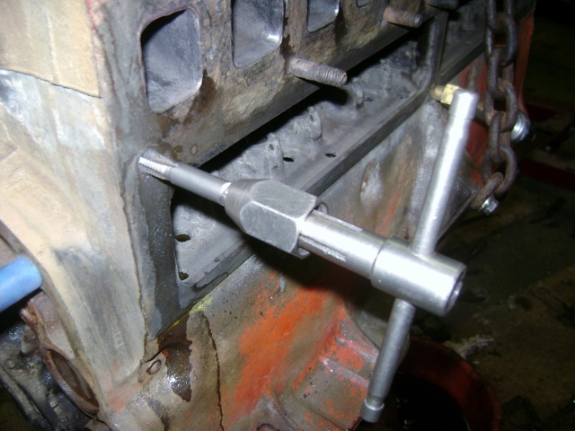
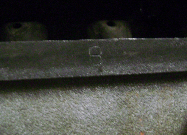
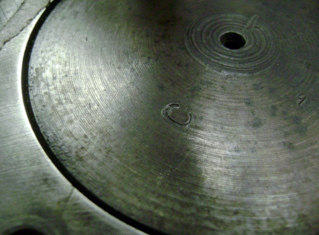
While cleaning up the block I found additional stampings that don't really correspond to the information I found in the manuals. maybe someone can shed some light on them.
The E and the 0 are at the rear of the lifter gallery and the B is stamped on the gasket surface of the lifter gallery at each pair of lifters. I thought they would correspond to the cylinder hone size but the pistons are C. I don't remember lifter bores being fitted to size.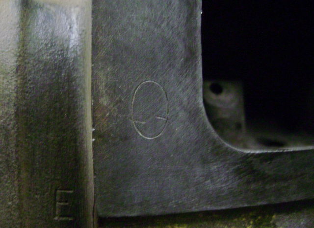
 0
0 -
Bill
I really hate to mention that I was taught that Hudson purposely put a slight 'Crown Radius' on the Tappets to help them rotate preventing cam lobe wear..
0 -
LOL, yep thought about that myself.
Then I looked at the lifters and figured a concave was worse than flat.
I also did some reading on flat tappet cams and noted that the cam lobe is cut to provide the rotation and an improper cut cam will lead to lifter failure. Lifter rotation was one of the checks during initial start up.
I also read a couple of older post here and during the engine build the lifters were ground flat vice replacing.
So.....
I just went with it.
I figure when I build my 308 it will get everything new so hopefully this one will last till that is done and ready to drop in.
?????
Thanks for the heads up.0 -
Bill
AFAIK radius ground tappets ie slightly convex were used by most engine makers in the stepdown and later era. The tappet actually rotates quite quickly, somewhere near camshaft RPM.
I really hate to mention that I was taught that Hudson purposely put a slight 'Crown Radius' on the Tappets to help them rotate preventing cam lobe wear..That's not to say a flat ground tappet didn't rotate and spread the wear, the radius grind just made sure that it happened.0 -
Here's a fairly good read.
Covers most of the bases concerning cam, lifter, installation, break-in, oils...etc.
http://www.enginebuildermag.com/2011/08/inside-flat-tappet-camshaft-andlifter-technology/
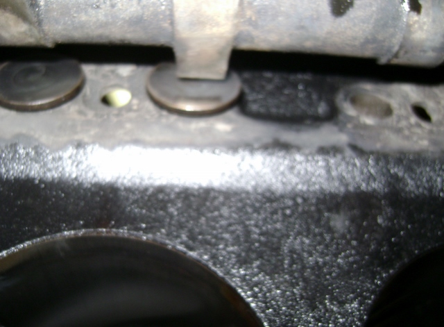
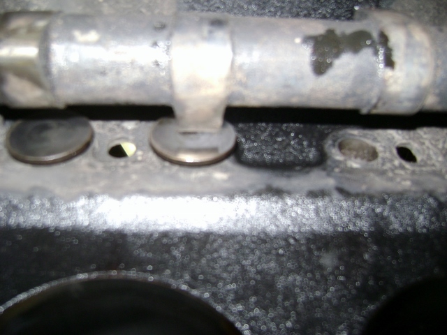
Just for my own curiosity I set a couple lifters in the holes and slipped the cam in to check lobe/tappet alignment.
I'll post the pics later when I head back in the house.0 -
Hudson cam followers were ground with a 2 degree radius.0
-
Thanks Geoff.
I checked the manuals and the supplements for specifics.
Do you have a reference or a copy you can post?
I took a couple quick pics of the cam lobe to lifter position.
You can see the lifters are off center on the lobes.
When I assemble the engine I will try to get some better pics.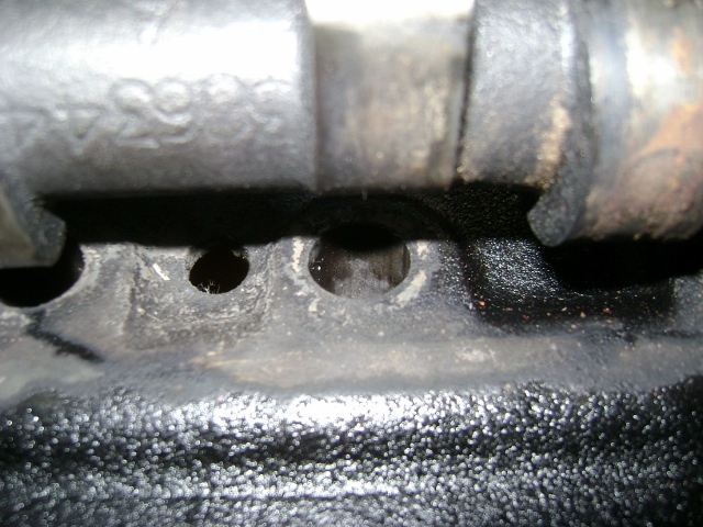
 0
0 -
I worked for a cam grinder some time ago, and got the specs from his data.0
-
Bill,
Your doing a very thorough job on this motor....enjoying the pictures...It will run so well you may never want to go to a 308....
0 -
Thanks Ol Racer. This is a first for me. I have never taken the short road on an engine build. But this wasn't supposed to be a rebuild, just a fix what's wrong and get it running!
But as the title says, Project Creep.
I have to keep my eye on the goal and just get this running and driving so I can sort everything else out and get ready for a build next winter.
I got a little more done.
I decided to replace the freeze plugs since I had no idea of the condition. They didn't look bad but like an IH, they rust from the inside out.
The main one that concerned me is the one you can't do with the engine installed and that's on the back of the block.
It's a 1" welsh type(you call them whatever you like).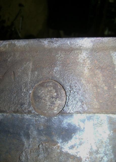
Drilled a hole in it.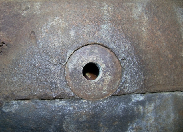
Popped it out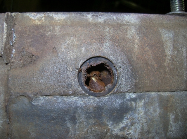
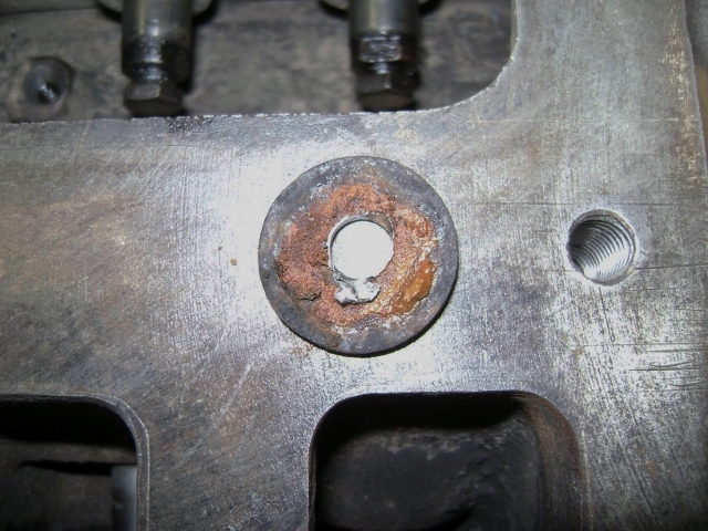
Cleaned up the hole and added my favorite freeze plug sealer, weather strip adhesive.
Then popped it back in.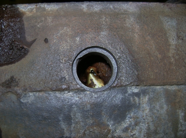
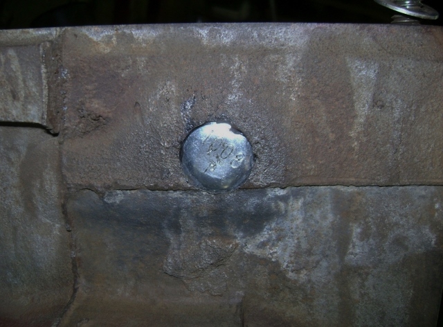
Then I used up about a case of brake cleaner and cleaned up the inside and outside some.
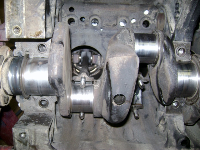
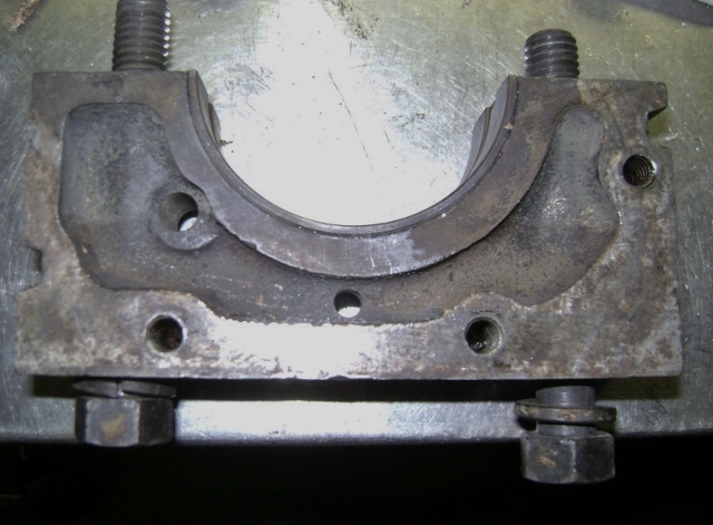
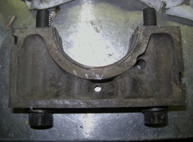
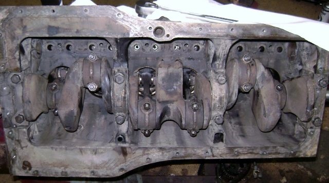
Then I installed the new rear main seal, crank, and then the nice yarn seals for the end caps.
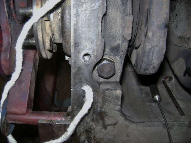
Oh, I also drilled the additional oil drain back hole in the front main. You can see the location for reference on the front and back side. I think I ended up fitting about 10" of yarn into each hole. I just followed the directions and added a little black RTV in the hole first and then "crowded" into the hole till it was packed tight.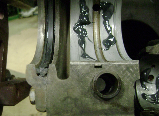
 0
0 -
Got a little more done.
I cleaned up the adjuster end of the lifters just so they are flat.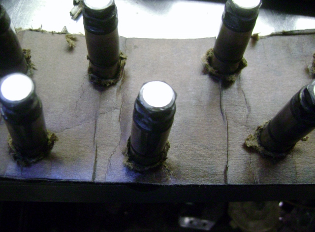
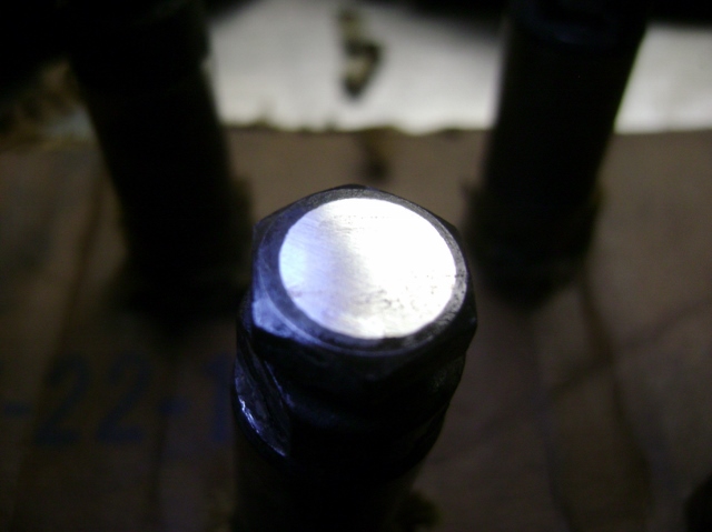
Then started to install the valves and springs.
I seriously thought about adding a spring shim but then talked myself out of it. I figured with the bottom end like it is, I might as well not try to make too much rpm or power with this thing. The valve springs can be my built in mechanical governor.
I also picked up a pair of retainer pliers to try. After playing with the retainers with the engine in the car I figured they couldn't hurt.
Once you get the hang of loading them, they actually work pretty well. Would definitely be of more value if the engine was still in the car.
I also found it much easier to install the springs while the cam and lifters were still out!!
I debated the installation sequence and glad I did it this way.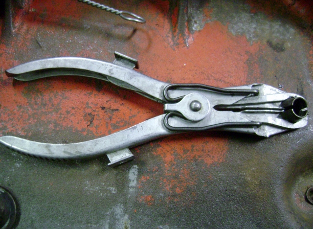
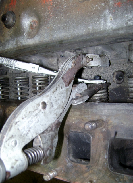
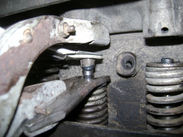
I got down to the last spring............
What's wrong with this picture?
No matter how hard you try....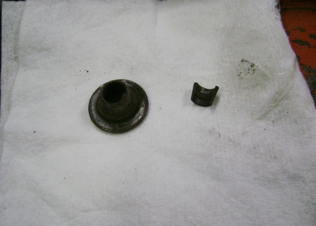 0
0 -
Hate it when that happens!!Course, having 1 too many wouldnt be good either.....Great work and really appreciate all the pics and documentation of your hard work!
Thanks.Jeff0 -
Fortunately I had the parts from the spare 308 so I could continue with the build.
I was kind of surprised none of the mature, experienced guys on here made any comment on the valves and springs going in before the cam and lifters.
Just to clarify, it's a little hard to slip the cam in the front of the block if the springs are pushing all the lifters down.
So you need to install the lifters, then the cam and then you can install the springs.
In the manual it talks about a special retainer that was available that you could turn the engine until the valve was full open then insert the metal clip to hold the lifter in that position and then rotate the engine until you have all the lifter help up out of the way. Then you can slide the cam out and in.
0 -
Yep, mine had 1 too many. Tearing my 308 down I found a valve keeper in the oil pan. Removal of the springs and valves showed none missing though. I guess no harm no foul.
0 -
Timing gears
This one took way longer than I thought it would.
I decided to go with the double roller chain and gears after seeing all the slop in the stock chain.
The new set didn't come with any directions so I opened the factory manual thinking the new set installed just like the original.
They also didn't have the new bolts so I had to run to Fastenal and grab some 3/8-16 x 1 1/2" grade 8 bolts.
I set the engine to TDC and started to line up the dots.
The double roller chain and gears come with marks on the chain at the 7 links apart and on the gears at the key way and the 0* tooth. The cam gear has 2 dots. one is a solid red and the other is just red in the center.
The crank gear is an adjustable with 3 keyways and the straight up dot is marked in white.
What I found is that when you set the engine to TDC the marks are no where close to where they can be lined up with the links in the chain.
So I removed both gears and set them on top of the stock gears and made my own yellow marks to correspond with the stock gears. I found the stock marks are about 60* different than the ones on the new set.
So I installed the new set using the new yellow marks on the gears and everything lined right up.
Then I rotated the engine over about 8 times and the found the new chain and gears marks came into alignment.
If you simply line up the crank white mark with the chain white link and the cam gear large red dot with the red chain link paying no attention to the piston location it will all line up.
But with so many variables, I just couldn't take that chance without verifying it for myself.
So now that I explained it, I will show you some pics to so you can see what I'm talking about.
I started with the front engine mount and gasket. Cleaning up all the bolts and getting them installed.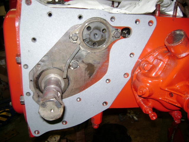
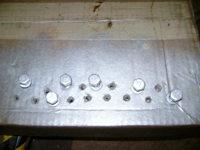
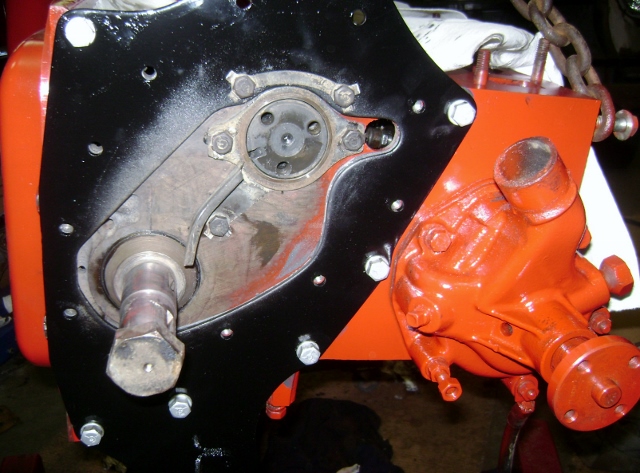
Here's the crank and cam gears showing the difference in the markings. The yellow marks are the ones I added to match the factory locations.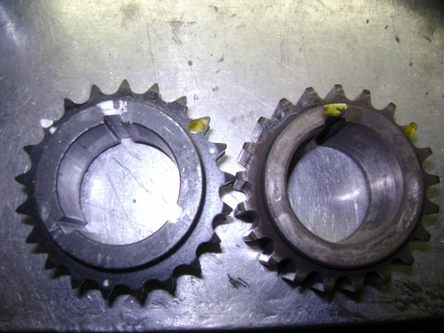
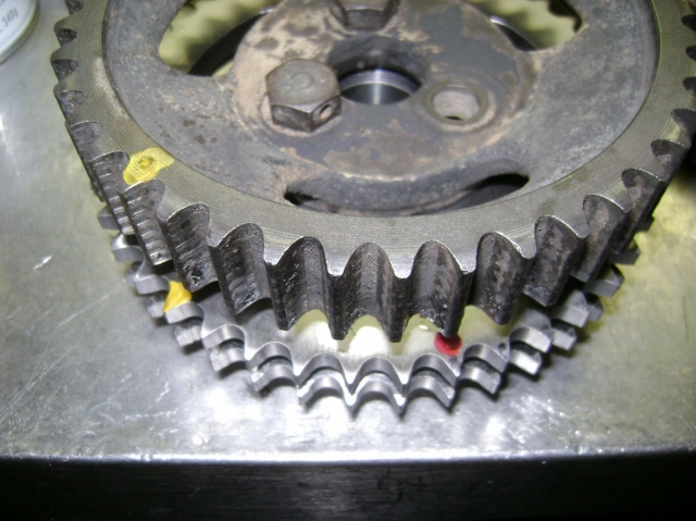
Something else I wanted to note is the diameter of the new gears are larger than the original. So when I installed the crank gear it actually hit the oil trough. So make sure you adjust it to clear.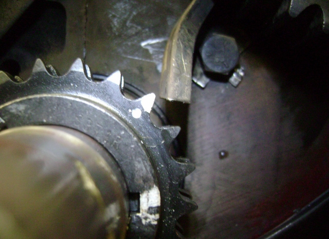
Here you can see everything installed and lined up with the engine at TDC and the factory marks (yellow) lined up. Note how far apart the new marks on the gears are away from the yellow.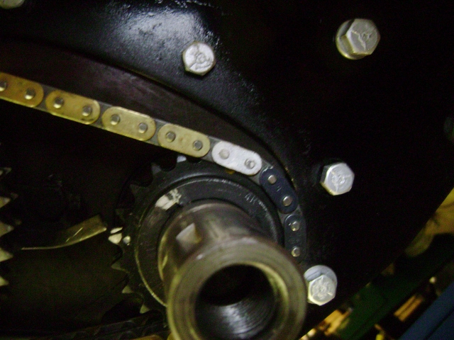
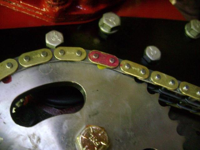
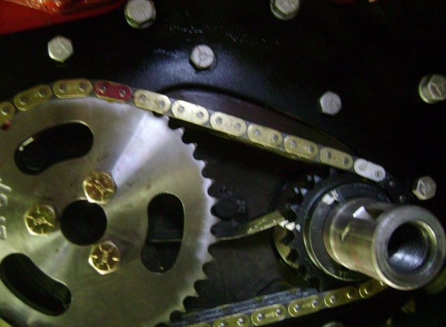
Then to satisfy my curiosity, I rotated the engine until the new roller marks actually lined up.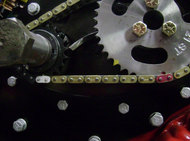
and this is where the piston actually sets in the cylinder if you just line up the double roller marks.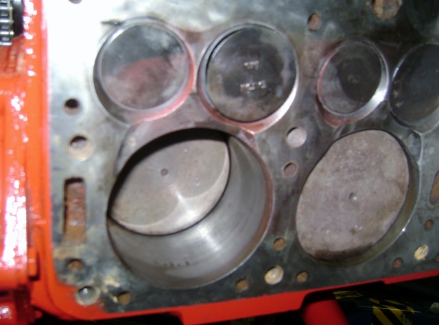
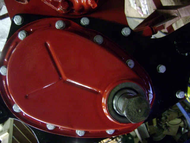
I installed the new seal, slipped the new spacer on the crank, and then bolted the timing cover on.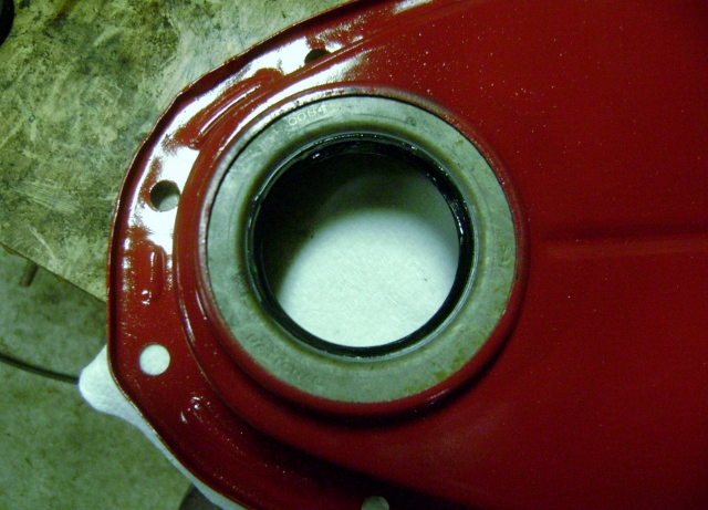
0 -
From BillUSN1 "But with so many variables, I just couldn't take that chance without verifying it for myself."
I can well understand that Bill, I'm sure I'd be double checking everything too.
Thanks again for this post. It takes time to produce a coherent write up and good photos don't just happen.
0 -
Bill, if you remember during our phone conversation I told you the set would be color coded. Glad you have time to check it. Further, if you check center line timing you will fine it 1 1/2 degree advanced.
Randy
0 -
Thanks Bob.
I just figure If I have a question then someone else probably has the same questions. So If I can't find the answer, I just figure it out and document it for the next guy.
I spent a little time going thru the oil pump, adding the new drive gear and then getting the oil pan buttoned up.
I disassembled and cleaned the oil pump housing and inspected the end plate and housing.
It's pretty normal to have some wear grooves on both due to the oil is unfiltered at this point. So any thing sucked up goes right thru the pump gears.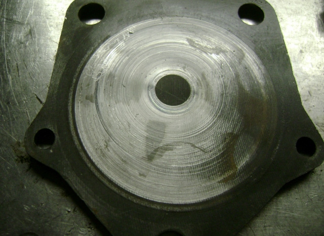
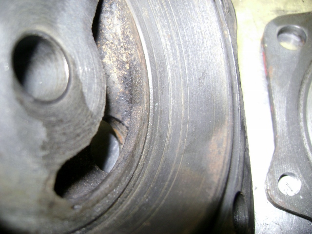
So I put a sheet of 400 grit wet or dry on a sheet of glass and used some WD40 and lapped the end plate and housing just to clean them up a little. I could have went more until the grooves were all gone but my fingers were wearing out.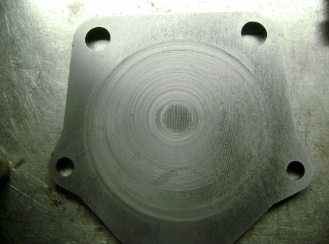
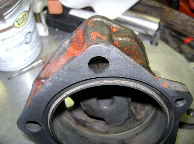
Then added the gasket and lube and started to assemble.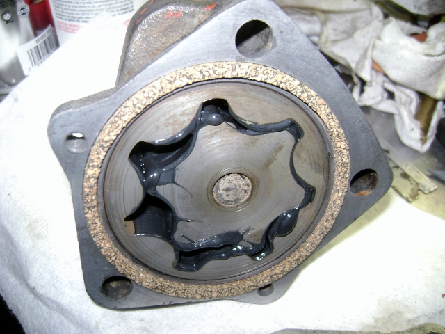
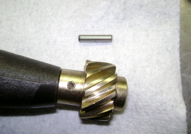
Assembled and added the new gear.
The new gear comes with 1 hole drilled about the same as the hole in the shaft at about 5/32-.156" but the pin supplied is a 3/16-.187".
So I chose to to stay with the smaller size and simply thru drilled at 5/32 and used a standard roll/split pin instead of drilling to the larger 3/16" and using the solid pin supplied. I wasn't sure if I could provide enough interference to retain the solid pin without needed to stake the tips.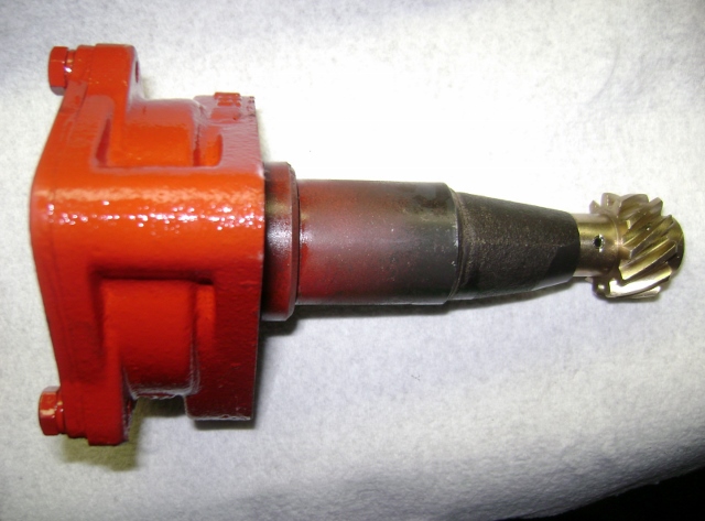
Then I sealed up the bottom end with the oil pan. Right or wrong...I set the pickup tube o-ring in the block and then set the gasket on top. The block had a taper machined in it so I felt that was best.
I didn't mention it earlier but I also added an o-ring to the pick up tube in the pan.
I removed the pick up cotter pin, cleaned the screen and then added an o-ring and reinstalled. The though was as the pump creats suction it will draw the pick up flange against the o-ring helping to prevent cavitation should the oil level be below joint.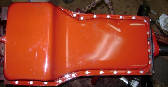
Interesting what you find as you clean parts.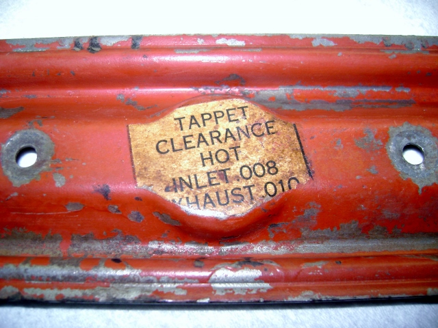 0
0 -
Bill, if you remember during our phone conversation I told you the set would be color coded. Glad you have time to check it. Further, if you check center line timing you will fine it 1 1/2 degree advanced.
Randy
Thanks Randy,
Yes it was color coded and fairly obvious once you figure it all out. The 2 red dots and not lining up on TDC like the manual states just caused me doubt.
So I had to verify.
My next build will get the cam dialed in. this one just needs to run. 0
0 -
Glad you are writing this engine build up in detail Bill. I had the same question you did about the timing chain-gear installation. This has been a help to me.0
-
Bill, as you know the original markings on the crank gear are not the same as the original hudson, Some get excited when they find three keyways.. The only thing similar is the the number of links in the chain where the timing marks on the gears are. I have a crank gear with 9 key way slots 0 + & - 2,4,6,8 degrees of advance or retard. for the isky racing cams. Really nice-don't have to worry about buttons for the cam gear but somewhat confusing to the novice. Nice setup compared the the original "morse setup" Keep up the good work. Maybe we will see you at French Lick. Hope you come
.
0 -
No problem on the crank gear. As noted earlier there was straight up, +4 and -4 slots.
I'm familiar with these from my old ford days running the cloyes double rollers.
I just needed to make sure I had the starting point correct.
No French Lick this year.
My show schedule is pretty much set for this year with the IH-International Harvester show schedule.
I saw that next year is in CO. The wife and I love CO. If there was interest from the organizers, I provide basic Fuel Injection Seminars at the IH shows. I could be talked into adding another for next year!
This year I'm scheduled for Spokane, WA, Brooks, OR, Salida, CO, Troy, OH and Grass Valley, CA....
It all starts the end of this month with my own Poker run here in Whidbey Island, WA.
0 -
You've gone this far..........don't do a half baked job. Have the crank reground and use new bearings. I'll bet I didn't need to say that. Go to "Wild Bill" in Tacoma.....tell him Frank sent you. Oh, wait.....don't tell him that. Also, resize the rods. You'll be surprised how far out of round they are.
Nice Timing chain...but typical of the Morse "Silent" chain. Get the Maas double row roller chain set-up, also a 21st Century Hudson item.0 -
Damn this thing!!! That's not the text that was supposed to go with the photo, in fact it's a post that I wrote about two months ago that just won't go away!
The text that I wrote for this photo should have said something like: I hate to see a guy go to this much time/effort/expense and then fire it off without the advantage of a full flow oil filtration system in place. Have a look at www.vintagefullflow.com and decide for yourself.
I just completed a run of adapters for the 232-262-308 although the site hasn't been updated to reflect that yet.
Frank0
Categories
- 37K All Categories
- 113 Hudson 1916 - 1929
- 20 Upcoming Events
- 93 Essex Super 6
- 28.6K HUDSON
- 576 "How To" - Skills, mechanical and other wise
- 995 Street Rods
- 151 American Motors
- 180 The Flathead Forum
- 49 Manuals, etc,.
- 78 Hudson 8
- 44 FORUM - Instructions and Tips on using the forum
- 2.8K CLASSIFIEDS
- 608 Vehicles
- 2.2K Parts & Pieces
- 77 Literature & Memorabilia
- Hudson 1916 - 1929 Yahoo Groups Archived Photos


